The six pins
Six pins, and every one of them gets a wire. GND and VCC, and four lines called A, B, C and D, one for each leg of the square switch in the middle. The switch never touches GND or VCC: it only ever joins two of the four lines to each other.
What is on the board
One square switch, four small LEDs, four resistors, and a six-pin header along the bottom edge. The header is right-angled, so the pins point out past the edge of the board and it lies flat in a breadboard or on a cable.
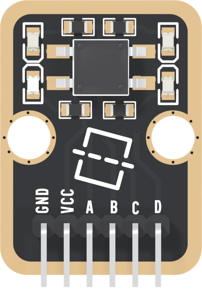
The switch is 6 mm square and a little over 3 mm tall. It has four legs, two out of each side, and each leg is one of the four lines. Beside every leg is an LED, and above or below each LED's leg a 1 kΩ resistor. The tilt icon printed under the switch is artwork.
The six names
GND is on the square pad. On this board it goes nowhere: the net list has it in a net by itself, because nothing here needs ground. Wire it anyway. It is the common ground between the block and your board.
VCC feeds the four LEDs through their resistors, and nothing else. The switch does not use it.
A, B, C and D are the switch's four legs. A is the lower-left leg, B the upper-left, C the upper-right and D the lower-right, looking at the parts with the header at the bottom. Each line also has its own LED.
Nothing here goes to ground
On a push button, one side of the contact goes to a supply, and your pin sees the other side change. This switch has no such side. When the board tips, a roller inside joins two of the four lines to each other, and that is all it does. A pin set to read one line sees nothing change.
So each of the four lines needs a GPIO, and the sketch has to ask the switch which two are joined: no line goes to ground is how. It also means this block's old page, which said a pin reading LOW showed its contact was closed, described a board that does not exist.
The back of the board

Turned over, the order reverses. The square pad is on the right, and it is still GND. The back prints TK19, the number on the box, and no pin names at all, so count from the square pad.
When it does not work
Hold the board with the parts facing you and the header pins pointing down. Read GND, VCC, A, B, C, D from left to right. GND is also the square pad, which is the one mark that survives when the board is in a breadboard and the labels are hidden.
No. Unlike most blocks in the kit, this one has no NC pin. The four lines need a GPIO each, VCC feeds the LEDs, and GND is the common ground with your board. Six wires.
Nothing. The net list puts the GND pin in a net of its own: no part on this board needs ground, because the switch only joins lines to each other. Wire it to your board's GND all the same, so the block and the board share a reference like every other block.
Because nothing is holding any line LOW yet. Each LED hangs from VCC onto one line and lights only when your board pulls that line LOW. With power alone they stay dark however you tip the board. The lights wait for you explains it.
What is inside the square switch, and which two lines it joins for each edge that goes down.
A roller and four corners →Edit this page — content/books/four-direction-tilt-sensor/the-six-pins.mdx
Questions about this product
See what other owners have asked, and read their solutions.
4-Direction Tilt Sensor
Loading discussions…
Discuss this article
Ask about this page. The answer stays here, on the page it belongs to, for whoever hits the same wall next.