The four pins
Four pins, three of them wired. GND is the square pad, VCC feeds the board's own 3.3 V regulator, SIGNAL switches the motor on when it is HIGH, and NC is connected to nothing. The small LED lights while the motor is being driven.
What is on the board
A coin motor, the parts that switch and feed it, and a four-pin header along the bottom edge. The header is right-angled, so the pins point out past the edge of the board and it lies flat in a breadboard or on a cable.
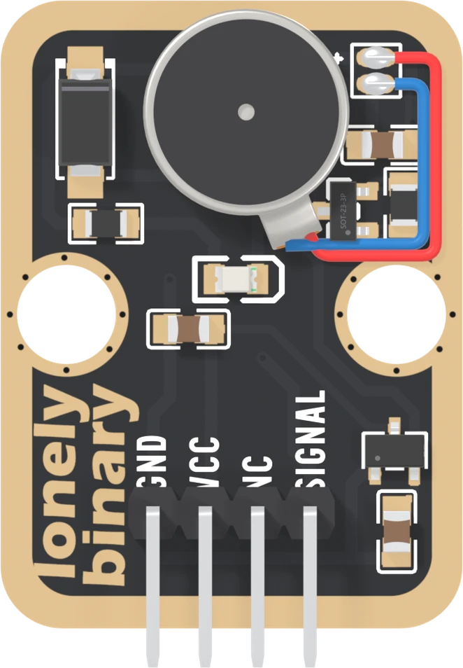
The motor is 10 mm across and 2.7 mm thick, lying flat on double-sided tape. Inside it a small weight sits off the centre of the shaft, and when it spins the whole disc shakes. That shake is the product. Everything else on the board is there to switch it and feed it.
The four names
GND is on the square pad. The motor's current returns through it, so it has to be the same ground as the board driving SIGNAL.
VCC goes to one place: the input of a 3.3 V regulator. The motor runs from the regulator's output, not from VCC, and nothing on the board connects VCC to SIGNAL. That is why this book wires VCC to 5V on every board, even a 3.3 V one. Why VCC can be 5V is the whole argument.
NC means not connected, and on this board it means it literally. The net list, which is the list of every electrical connection on the board, does not mention it at all.
SIGNAL is the gate of a MOSFET, a transistor used as a switch, with a 10 kΩ resistor to GND. HIGH turns the motor on, LOW turns it off, and left unconnected it stays off. It carries none of the motor's current.
The light
The small LED in the middle lights while SIGNAL is HIGH and the switch is closed. It is lit by the same current path as the motor, from the board's 3.3 V, so it is a quick check that power and SIGNAL both arrived. It is not proof that the motor turned: when it does not buzz uses exactly that difference.
The back of the board
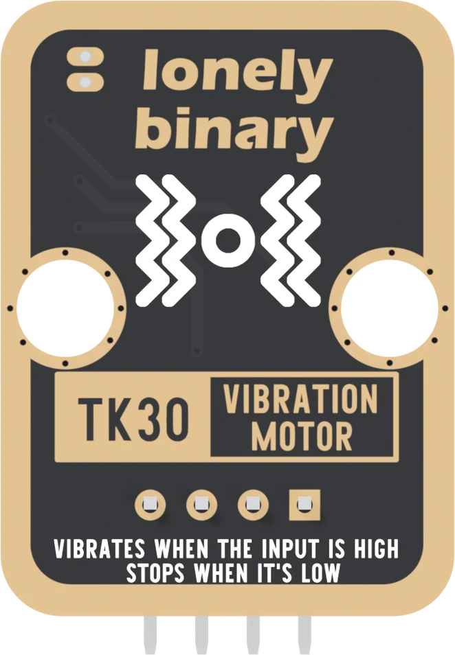
Turned over, the order reverses. The square pad is on the right, and it is still GND. The back prints TK30, the number on the box, and the whole of the logic in two lines: vibrates when the input is high, stops when it is low. It prints no pin names.
When it does not work
Hold the board with the parts facing you and the header pins pointing down. Read GND, VCC, NC, SIGNAL from left to right. GND is also the square pad, which is the one mark that survives when the board is in a breadboard and the labels are hidden.
No. It is not connected to anything on the board. It is there so every TinkerBlock block has the same four-pin header and one cable fits all of them. Wiring it does no harm and changes nothing.
Yes. The motor has double-sided tape on its back from the factory, and it is laid flat on the board with its red and blue leads soldered to two pads marked + and −. The tape is how the shake gets into the board and from the board into whatever it is fixed to.
It needs an output, not an input. Any digital pin that can be set HIGH turns the motor on; a pin that can also do PWM lets you set its strength. On an Uno that means pins 3, 5, 6, 9, 10 or 11; this book uses 9.
Edit this page — content/books/vibration-motor/the-four-pins.mdx
Questions about this product
See what other owners have asked, and read their solutions.
Vibration Motor
Loading discussions…
Discuss this article
Ask about this page. The answer stays here, on the page it belongs to, for whoever hits the same wall next.