The four pins
Four pins, three of them wired. GND and VCC power the chip, SIGNAL tells your board whether a magnet is near, and NC is connected to nothing. A magnet makes SIGNAL read LOW: the board says ACTIVE LOW, and it means it.
What is on the board
A Hall effect chip, two small resistors, a capacitor, a red LED, and a four-pin header along the bottom edge. The header is right-angled, so the pins point out past the edge of the board and it lies flat in a breadboard or on a cable.
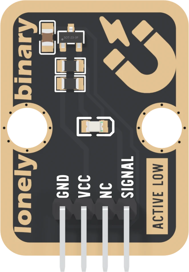
The chip is a CrossChip CC6201, about 3 mm long, with one leg on top and two below. It is the only part that feels a magnet. Below it are the 10 kΩ pull-up and the 1 kΩ for the LED, and the LED sits alone in the middle of the board. The capacitor beside the chip, 100 nF, steadies its supply.
The large gold magnet at the top right is printed artwork. Hold a magnet over it and nothing happens. Hold it over the chip.
The four names
GND is on the square pad. The chip and its capacitor return here.
VCC powers the chip, and also feeds the pull-up and the LED. With no magnet near, SIGNAL sits at VCC, which is why the next article exists.
NC means not connected, and on this board it means it literally. The net list, which is the list of every electrical connection on the board, does not mention it at all.
SIGNAL is the chip's output. No magnet: HIGH. A magnet near the chip, either pole: LOW, and the red LED lights. The silkscreen says so on the front, ACTIVE LOW.
Low means a magnet
That is the one thing to remember about this block, and the page it replaces said the opposite. A sketch that treats HIGH as "magnet" reports a magnet all the time there is none. Active low, and the light shows why the chip works that way round.
The back of the board
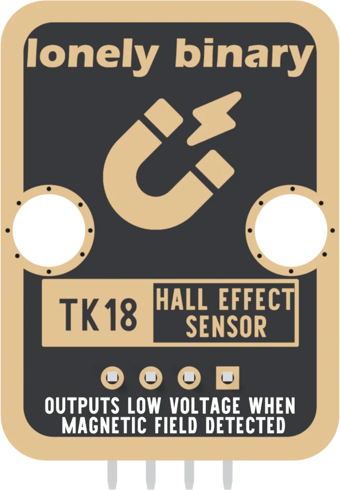
Turned over, the order reverses. The square pad is on the right, and it is still GND. The back prints TK18, the number on the box, and OUTPUTS LOW VOLTAGE WHEN MAGNETIC FIELD DETECTED: the same rule in a sentence.
When it does not work
Hold the board with the parts facing you and the header pins pointing down. Read GND, VCC, NC, SIGNAL from left to right. GND is also the square pad, which is the one mark that survives when the board is in a breadboard and the labels are hidden.
Over the small black three-legged chip at the top left, beside the brown capacitor, with a flat face of the magnet towards it. The magnet printed in gold at the top right is only a picture; nothing under it senses anything.
No. It is not connected to anything on the board. It is there so every TinkerBlock block has the same four-pin header and one cable fits all of them. Wiring it does no harm and changes nothing.
No. That sketch came from this block's old page, which had it backwards. The chip pulls SIGNAL LOW when it sees a magnet, the front of the board says ACTIVE LOW, and the back says OUTPUTS LOW VOLTAGE WHEN MAGNETIC FIELD DETECTED. Test for LOW.
Why the block's VCC pin goes to 3V3 beside an ESP32 and 5V beside an Uno.
VCC sets the level →Edit this page — content/books/hall-effect-sensor/the-four-pins.mdx
Questions about this product
See what other owners have asked, and read their solutions.
Hall Effect Sensor
Loading discussions…
Discuss this article
Ask about this page. The answer stays here, on the page it belongs to, for whoever hits the same wall next.