What is where
The long TinkerBlock board, 62.4 × 30.4 mm with a hole in each corner. The stick fills the left half, two small red buttons sit in the middle, four larger ones make a diamond on the right, and the resistors that make the buttons work run along the top edge. No LED.
A long board
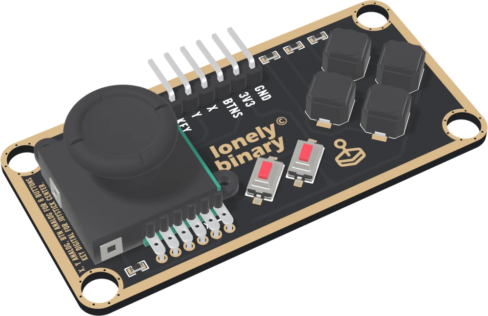
Most TinkerBlock boards are 22.4 × 30.4 mm with two mounting holes. This one is 62.4 × 30.4 mm with four, one in each corner, because a thumb stick is pushed around and a board held at two points rocks. The header sits in the middle of the top edge, and its pins are bent at a right angle so they point out past the edge and the board lies flat.
Four groups of parts
The stick takes the left half. Its housing is about 18 mm square and its cap, 14.8 mm across, stands about 13.5 mm above the board, much taller than anything else here. The supplier's drawing gives a tilt of about 16° each way. Its six legs are soldered along the bottom edge.
The red pair are two small tact switches, 3 × 6 mm, turned 45° at the bottom middle: U11 on the left, U10 on the right.
The diamond is four larger tact switches, 6 × 6 mm, on the right, set out like the face buttons of a game pad: U8 at the top, U7 on the left, U6 on the right and U5 at the bottom.
The resistors are the small parts along the top edge, three at each end, and one more, R1, at the bottom left by the stick's legs. All seven are the same 10 kΩ part. The six along the top are the ladder that puts six buttons on one pin; R1 holds KEY LOW.
What is not here
No LED, no chip, no NC pin. Every part on the board is a switch, a potentiometer or a resistor. The header is printed 3V3, and this book follows the print on every board it plugs into.
When it does not work
Each switch has its designator printed beside it: U11 and U10 are the red pair, left and right; U8, U7, U6 and U5 are the top, left, right and bottom of the diamond. This handbook uses those names, because they are the ones on the board.
There is no LED on this board, so nothing lights at all. The only way to see that it has power is to read it: the stick let go should read near the middle of the scale, not 0 and not the top.
It is the long board, 62.4 mm across, not the 22.4 mm of the small blocks. The four mounting holes are 4.8 mm across, one in each corner, 3.2 mm in from both edges. Mount it by all four; the stick is pushed hard, and two holes let it rock.
The shop pictures do. The board itself prints only U5 to U11 beside the switches, and nothing in the circuit makes one a start button. Give them whatever jobs your project needs; the ladder decides only which one wins when two are pressed.
What is inside the stick, and why each axis is a voltage near the middle.
Two pots in one stick →Edit this page — content/books/slim-joystick/what-is-where.mdx
Questions about this product
See what other owners have asked, and read their solutions.
Slim Joystick
Loading discussions…
Discuss this article
Ask about this page. The answer stays here, on the page it belongs to, for whoever hits the same wall next.