The four pins
Four pins, three of them wired. GND and VCC power the board, SIGNAL is a voltage that rests at one level and swings above and below it when there is sound, and NC is connected to nothing. There is no LED: nothing on the block lights to say it is working.
What is on the board
A microphone capsule in a foam ring, eight small parts round it, and a four-pin header along the bottom edge. The header is right-angled, so the pins point out past the edge of the board and it lies flat in a breadboard or on a cable.
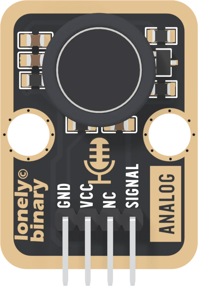
The capsule is an electret microphone, 9.7 mm across, and the only part that hears anything. The small parts are its supply, its filters and a one-transistor amplifier. A capsule and one transistor goes through them.
The four names
GND is on the square pad. The capsule's ground lead, the transistor's emitter and three of the small parts end here.
VCC feeds three resistors: one powers the capsule, one biases the transistor, and SIGNAL hangs from the third. Match it to your board: 3V3 beside an ESP32, ESP32-S3 or Pico, 5V beside an Uno. A loud sound can take SIGNAL up to VCC itself.
NC means not connected, and on this board it means it literally. The net list, the list of every electrical connection on the board, does not mention it.
SIGNAL is the transistor's output. In silence it rests at one voltage, somewhere between the rails, and sound makes it swing above and below that voltage. It goes to an analog pin, not a digital one. It is not a loudness level: louder does not simply mean higher.
No light on the board
Some TinkerBlock blocks carry an LED that shows what the output is doing. This one does not, and it has no comparator either, so there is no on-off output and no knob to set one. The first reading is the test: a still line in the Serial Plotter that jumps when you clap.
The back of the board
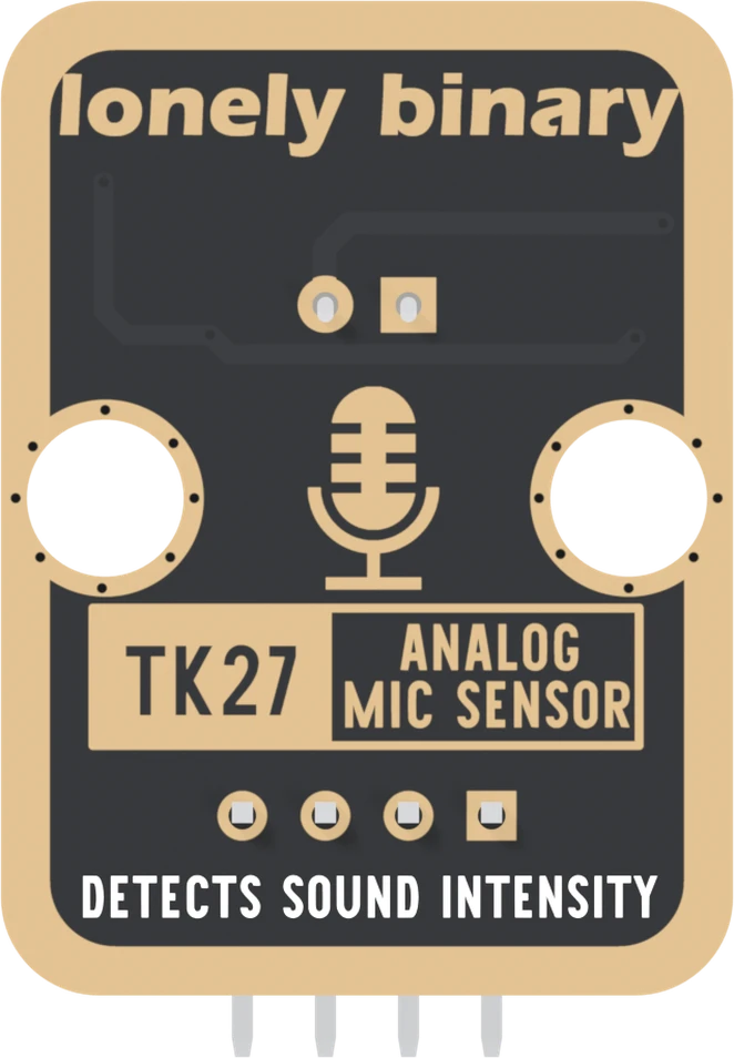
Turned over, the order reverses. The square pad is on the right, and it is still GND. The back prints TK27 ANALOG MIC SENSOR and DETECTS SOUND INTENSITY, but no pin names. The intensity is something your sketch works out from the swing; the board itself only passes the swing on.
When it does not work
Hold the board with the parts facing you and the header pins pointing down. Read GND, VCC, NC, SIGNAL from left to right. GND is also the square pad, which is the one mark that survives when the board is in a breadboard and the labels are hidden.
No. It is not connected to anything on the board. It is there so every TinkerBlock block has the same four-pin header and one cable fits all of them. Wiring it does no harm and changes nothing.
There is no LED on this board, so you cannot tell by looking. Run the first-reading sketch with the Serial Plotter open and clap near the capsule. A line that sits still and then jumps up and down on the clap means it is powered and working.
It comes off, but leave it on. It keeps breath and draughts off the capsule, which would otherwise read as loud low thumps. It does not change what the circuit does with sound that reaches it.
Every part on the board and the job it does. There is no op-amp, whatever the old page said.
A capsule and one transistor →Edit this page — content/books/analog-microphone/the-four-pins.mdx
Questions about this product
See what other owners have asked, and read their solutions.
Analog Microphone
Loading discussions…
Discuss this article
Ask about this page. The answer stays here, on the page it belongs to, for whoever hits the same wall next.