The six pins
Six pins, and two of them do nothing at all. GND is the square pad, and RED, GREEN and BLUE each drive one colour through its own resistor. There is no supply pin: the three pins your sketch drives are the LED's power.
What is on the board
Five parts. A square white LED 5 mm across, three small resistors in a row under it, and a six-pin header along the bottom edge. The header is right-angled, so the pins point out past the edge of the board and the board lies flat.
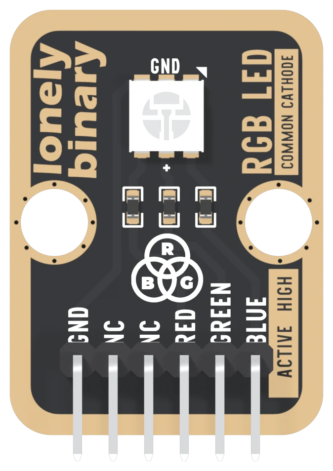
The LED looks like one part, and it is three: a red, a green and a blue LED in one package behind a white diffuser. Each has its own resistor on the board, 1 kΩ, and its own pin on the header.
The six names
GND is the return path for all three colours, on the square pad. Every LED's cathode is joined to it on the board.
NC means not connected, and on this board it means it literally. The net list, which is the list of every electrical connection on the board, does not mention either NC pin at all.
RED, GREEN and BLUE each go through a 1 kΩ resistor to one LED's anode. Nothing else sits between the pin and the LED. Set a pin HIGH and its colour lights; LOW and it goes out. The front says so in two places: ACTIVE HIGH beside the header and COMMON CATHODE up the edge.
There is no supply pin
As on the XL LED, the pins you drive are the power. The current for red comes out of the pin wired to RED, and so on. That keeps the wiring to four wires, and it has one consequence the XL LED did not have: the three colours do not react equally when the pin voltage changes. Chapter 3 is about that.
The back of the board
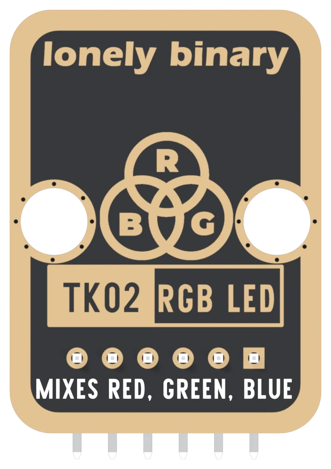
Turned over, the order reverses. The square pad is on the right now, and it is still GND. The back is where the part number is printed, TK02, the number on the box and the address of this block's page.
When it does not work
Hold the board with the LED facing you and the header pins pointing down. Read GND, NC, NC, RED, GREEN, BLUE from left to right. GND is also the square pad, which is the one mark that survives when the board is in a breadboard and the labels are hidden.
No. They are not connected to anything on the board, on either side. The net list does not mention them. Wiring them does no harm and changes nothing.
There isn't one. Each colour is powered by its own pin: when your sketch sets RED HIGH, that pin supplies the red LED's current. That is also why the colours depend on your board's logic voltage, 5 V on an Uno and 3.3 V on an ESP32.
Turned over, the order reverses: BLUE is on the left and GND on the right, and GND is still the square pad. The back prints MIXES RED, GREEN, BLUE instead of the names. Count from the square pad and you cannot get it backwards.
The words printed up the edge of the board, and what they mean for which way round your sketch works.
What common cathode means →Edit this page — content/books/rgb-led/the-six-pins.mdx
Questions about this product
See what other owners have asked, and read their solutions.
RGB LED
Loading discussions…
Discuss this article
Ask about this page. The answer stays here, on the page it belongs to, for whoever hits the same wall next.