The sender, pin by pin
An infrared LED, a transistor to switch it and one resistor to limit it. The resistor is fixed at 150 Ω, so the one thing you decide about this board's range is which rail its VCC goes to, and 5 V buys about a third more than 3.3 V.
What is on the board
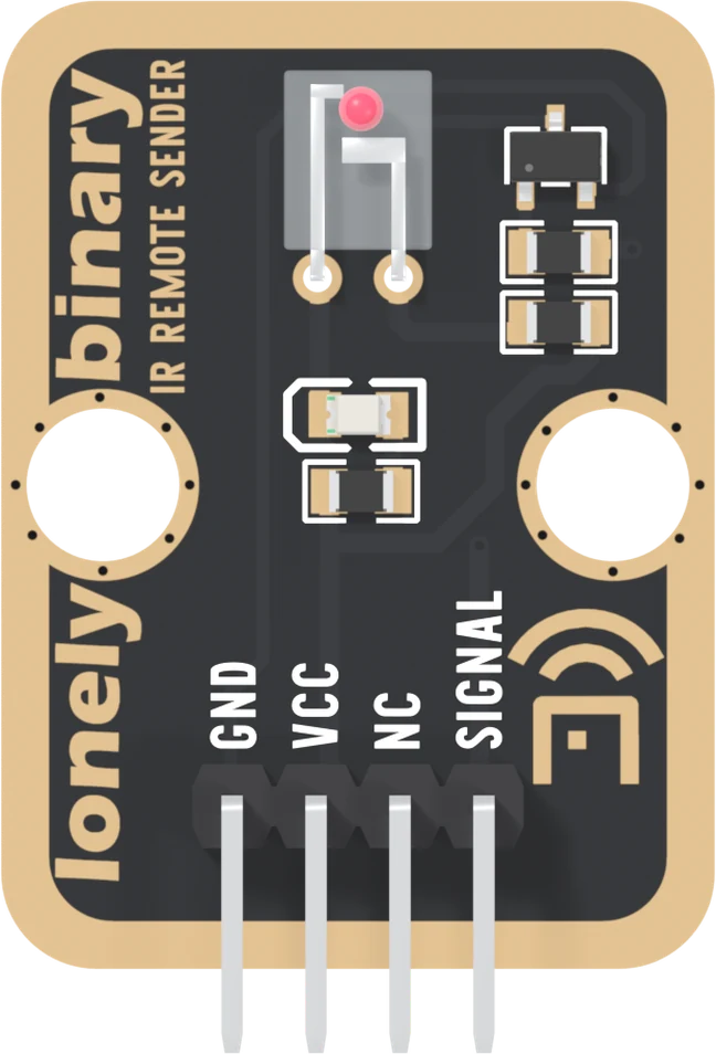
An Everlight IR908-7C infrared LED, an S8050 transistor, 150 Ω in series with the LED, 1 kΩ into the transistor's base, and a red LED with its own 1 kΩ. No chip, no oscillator, nothing to set up. It is a switch with an LED behind it.
The IR908-7C is a sidelooker: it shines out of one side of its clear package, not out of the end. On this board its legs are bent so it lies flat with that side facing up, so like the receiver it looks out of the parts side of the board. Point that side at the receiver.
The four pins
GND is the square pad and the transistor's emitter. VCC feeds both LEDs through their resistors and nothing else. NC is connected to nothing. SIGNAL goes through 1 kΩ to the transistor's base, and it is active HIGH: HIGH turns the transistor on and both LEDs light. That is the opposite of the receiver, and it is IRremote's default, so nothing needs setting.
Where the current comes from
Your pin does not light the LED. It puts a couple of milliamps into the transistor's base, and the transistor lets VCC push the LED's current through to GND. The transistor needs about a twentieth of what a 3.3 V pin gives it, so a 3.3 V board drives a sender on 5 V with nothing in between.
What the rail decides
The 150 Ω is fixed and the LED drops about 1.25 V whatever you do, so the current is what is left of VCC divided by 150: about 13 mA from 3.3 V and 24 mA from 5 V. Reach follows the square root of current, so 5 V buys about a third more distance than 3.3 V. It is the biggest thing you can do for range, and it costs one wire.
Both currents are inside the LED's 50 mA continuous rating. Keep VCC at 5 V or below: the resistor is the only limit.
The beam is the narrow one
The IR908-7C's beam is 40° in all, ±20° either side of straight on, against the receiver's ±45°. The receiver looks like the fussy half because it has the chip; in practice the sender is the one you aim. How far, and how wide draws both.
When it does not work
You cannot see it: 940 nm is outside what an eye responds to. Point a phone camera at the clear LED; most show it as a faint flicker. The red LED beside it is on the same transistor, so it flickers whenever the infrared one does, dimly from 3.3 V.
Yes, and it is the combination to use. The pin only supplies base current through 1 kΩ, about 2.6 mA from 3.3 V; the LED's 24 mA comes from the 5 V rail through the transistor. VCC never reaches SIGNAL, so nothing needs level shifting.
On an Uno, no: IRremote makes the carrier in software on any pin. On an ESP32, ESP32-S3 and Pico it uses a hardware PWM channel by default, which also works on any pin. Receiving is what takes Timer2 on an Uno.
Not safely past 5 V. Nothing but the 150 Ω resistor limits the LED's current, and TinkerBlock blocks are built for 3.3 or 5 V. More range comes from 5 V instead of 3.3, from aiming, and from shade on the receiver.
It should not. From 5 V the LED takes about 24 mA, half its 50 mA continuous rating, and while sending the carrier keeps it on less than a third of the time.
A sketch that sends a code you captured, and the one line that decides whether it works.
Be the remote →Edit this page — content/books/ir-receiver/the-sender-pin-by-pin.mdx
Questions about this product
See what other owners have asked, and read their solutions.
This page covers several products. Choose yours to see the right discussions.
Discuss this article
Ask about this page. The answer stays here, on the page it belongs to, for whoever hits the same wall next.