Two sets, one board
The clock set and the digit set are the same board with a different display soldered to it: one has a colon between the middle digits, the other a decimal point after each. That one difference decides what a bit in your sketch does.
The same board twice
Both six-packs are the TK51: the same PCB, the same chip, the same four pins. What differs is the display soldered to the front of it.
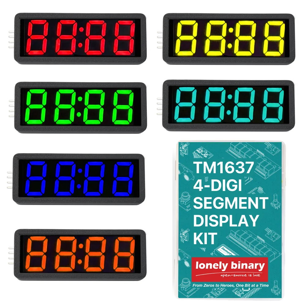
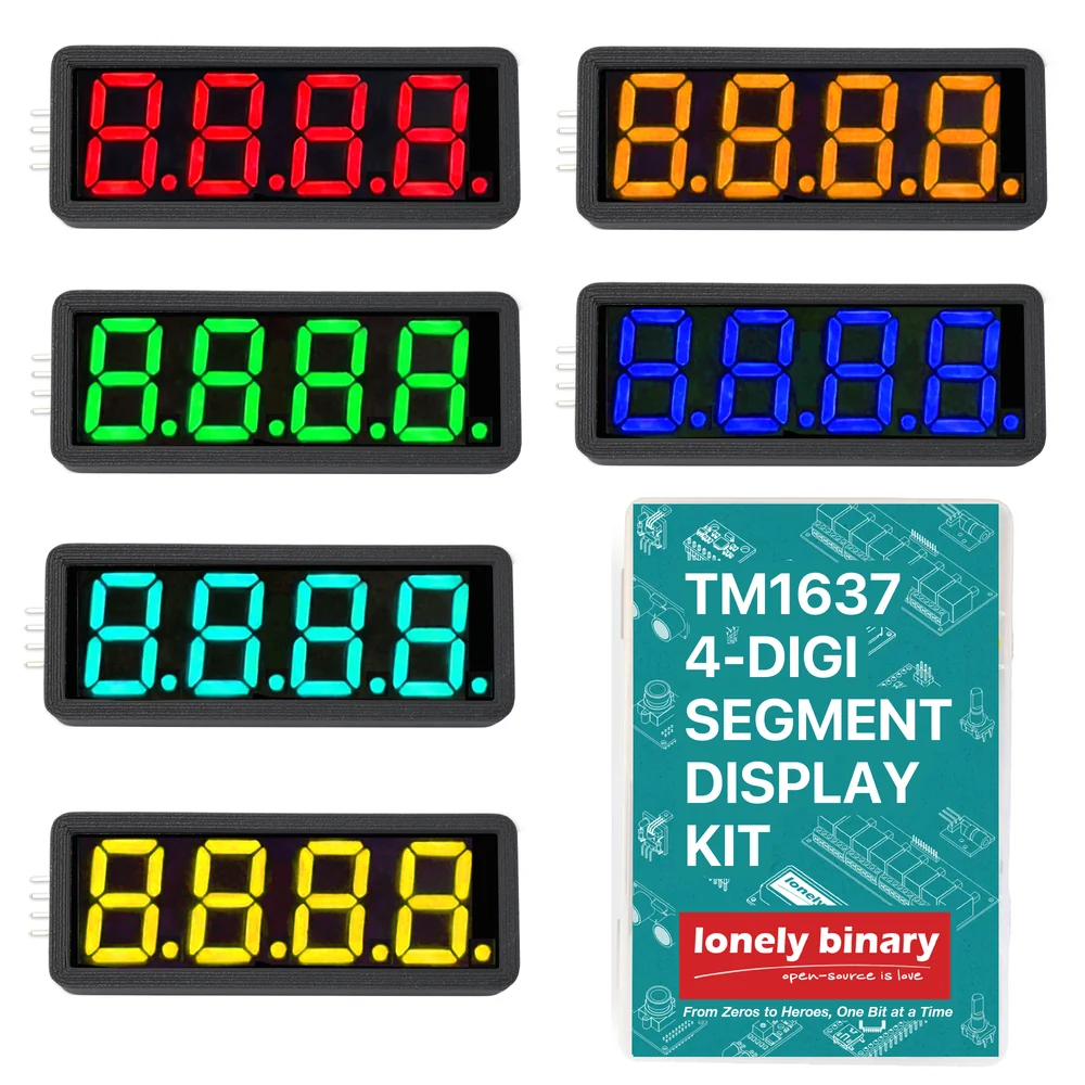
The board itself says so. Printed across the back, above the model number: FOR CLOCK DISPLAY, DECIMAL POINTS ARE REPLACED BY COLON. There are eight segment wires and the eighth is the point — so a panel that spends it on a colon has none left for points.
One bit, two meanings
The library gives you a dots argument: eight bits, one per digit, counted from
the left. Set a bit and that digit's point lights.
On the clock panel, three of those four bits light nothing at all, because there is no LED there to light. The fourth — the second digit's — is wired to the colon.
0b01000000 is what lights it — not 0b10000000, which is the first digit and, on a clock panel, nothing at all. On the digit panel the same bit puts a point after the second digit.That is the entire difference between the two sets, and it is the source of
nearly every "the colon won't work" question. The colon is
0b01000000, the second digit. Older tutorials, this shop's included, have
said 0b10000000, which is the first digit and does nothing whatsoever on a
clock panel.
Which set to buy
Pick by what the number means, not by which looks better.
| You are showing | The set | Why |
|---|---|---|
| A time, a timer, minutes and seconds | Clock | The colon is the only separator that reads as a time |
| A temperature, a voltage, a weight | Digit | 23.5 needs a point, and a colon cannot be one |
| A count, a score, a raw number | Either | Neither separator is used |
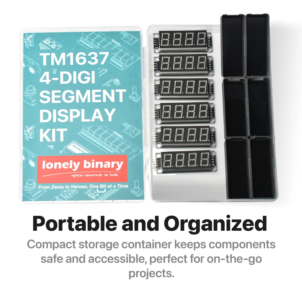
The headers come soldered on, so nothing here needs an iron. Both sets are six panels in six colours, one of each, with a smoked film cover and a 3D-printed enclosure for every one. The colour is not just decoration: which colours are usable depends on the voltage you can feed them, which is 3.3 V or 5 V.
When it does not work
On a digit panel, yes, but the separator is a decimal point sitting low between the digits rather than a colon: 12.34 instead of 12:34. It reads as a number, not a time. Most people find that is exactly one compromise too many for a clock on a shelf.
Not with a point, because it has none. The usual dodge is to display 3.30 V as 330 and put a printed label beside the display, or to use the colon as a separator for something where that reads naturally — minutes and seconds, or a score.
Look at yours: the panel is whatever is soldered on, and the board underneath is identical either way. Whichever it is, bit 7 of the second digit is the bit that either lights the colon or puts a point after that digit.
In principle — it is a 12-pin through-hole display in the same footprint — but it means desoldering twelve pins from a board with the display sitting flat over them, which is fiddly enough that buying the other set is usually cheaper than the attempt.
Four pins, four spare holes, and what is hiding under the display.
The board, pin by pin →Edit this page — content/books/tm1637-display/two-sets-one-board.mdx
Questions about this product
See what other owners have asked, and read their solutions.
This page covers several products. Choose yours to see the right discussions.
Discuss this article
Ask about this page. The answer stays here, on the page it belongs to, for whoever hits the same wall next.