The six pins
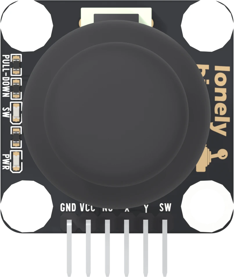
Six pins along the bottom edge: GND, VCC, NC, X, Y and SW, with GND on the square pad at the left. Five get a wire. X and Y are analog, SW is a digital click, and NC goes nowhere at all.
Three inputs on six pins
The stick counts three times: it tilts along two axes and clicks when you press it straight down. So it gives three readings, X, Y and SW, and the header adds the supply, GND and VCC, and one pin that goes nowhere, NC. The header is six right-angle male pins at 2.54 mm pitch, pointing out past the bottom edge, so a jumper wire's housing pushes straight on.
The six names
Pick a pin and the figure rings it and says what it reaches on the board. Five of the six get a wire: two to power, two to analog inputs and one to a digital input. NC gets none.
GND is on the square pad, at the left-hand end. It is the one mark that tells six identical holes apart, so count from it.
VCC is the supply, and it is also the ceiling of every other pin: X and Y reach it at the ends of the travel, and SW is joined to it on every click. Wire it to your board's own logic voltage, 5V on an Arduino Uno and 3V3 on an ESP32, an ESP32-S3 or a Raspberry Pi Pico. VCC sets the top is why.
NC is in no net. It keeps GND, VCC, NC and the first signal where the four-pin TinkerBlocks put them, and nothing else.
X and Y are the stick's two axes. Each is the wiper of a potentiometer whose track runs from VCC to GND, so each is a voltage that rests near the middle and follows the tilt. Each needs an analog pin.
SW is the click. It reads LOW at rest and HIGH while the stick is pressed, because a resistor on the board pulls it down and the switch joins it to VCC. A digital pin reads it.
The back of the board
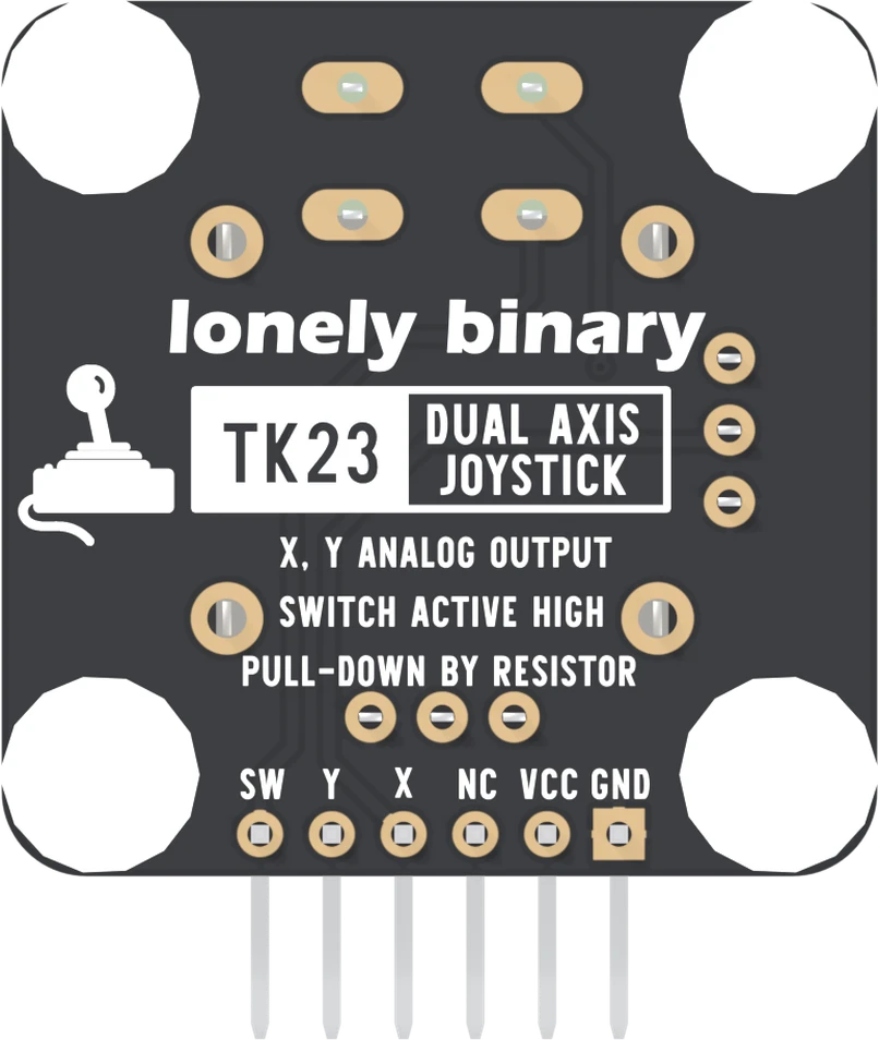
Turned over, the order reverses and the square pad moves to the right. The back also prints the three facts this book keeps coming back to: X and Y are analog, the switch is active HIGH, and a resistor pulls it down.
When it does not work
Hold the board parts up with the header along the bottom edge. Read GND, VCC, NC, X, Y, SW from left to right. GND is the left-hand end, and it is the square pad, which you can still see when the printed names are hidden by a wire.
No. NC is in no net on the board: its pad is soldered and no trace leaves it. Wired or left empty, nothing changes. Leave it empty, so a jumper cannot land there by mistake and leave X or SW unwired.
They are the same pins seen from behind. Turned over, the back reads SW, Y, X, NC, VCC, GND from left to right, and the square pad is on the right. It is still GND. Count from it.
Yes, analog pins can read digital levels too, but it spends a pin you may want later. SW is only ever 0 V or VCC, so any digital input reads it; keep the analog inputs for X and Y.
The stick, its two potentiometers, the switch, and the two lights up the left edge.
What is where →Edit this page — content/books/dual-axis-joystick/the-six-pins.mdx
Questions about this product
See what other owners have asked, and read their solutions.
Dual Axis Joystick
Loading discussions…
Discuss this article
Ask about this page. The answer stays here, on the page it belongs to, for whoever hits the same wall next.