A roller and four corners
Inside the square switch is one metal roller in an eight-sided cell, with a contact in each corner. Tip the board and the roller rolls to the low side, where it rests across that side's two contacts and joins them. Four edges, four pairs: A–B, B–C, C–D and D–A. The diagonals never join.
One roller, four contacts
The switch is an RB-6635S-1T: a 6 mm square, 3.5 mm tall. Its maker's drawing shows the inside as an eight-sided cell with a knurled metal roller loose in it, and a contact at each of the four corners. Each contact is one leg, and each leg is one of the lines A, B, C and D.
The roller has nothing to hold it but gravity. Tip the board and it rolls downhill until it meets the low side of the cell. Every side has a contact at each end, so the roller comes to rest across two of them and joins them electrically. That is the whole switch.
Which pair for which edge
Pick the edge that goes down. Hold the board flat, parts up and header at the bottom, then tip it:
| Edge that goes down | The roller joins | The sketches call it |
|---|---|---|
| Left | A and B | left |
| Top, away from the header | B and C | top |
| Right | C and D | right |
| The header edge | D and A | header |
Those are the four pairs the maker's drawing shows: two contacts that share one side of the package. A and C sit in opposite corners, and so do B and D. No side has both, so no position of the roller joins them.
What that rules out
Two opposite sides at once. One roller can only be on one side, so left and right can never read together, nor top and header. This block's old page said two sides close together near a diagonal. Tipped towards a corner, the roller lands on one side or the other, or rests against the single contact in the corner and joins nothing.
An angle. The switch has four answers, and none. Its drawing gives no trip angle, and this book does not guess one. For how far the board is tilted, not just which way, you need an accelerometer.
Knowing it is level. The roller is not sprung back to the middle, so a level board keeps whatever it last rolled to. Level is not a reading is about that.
Where the legs are
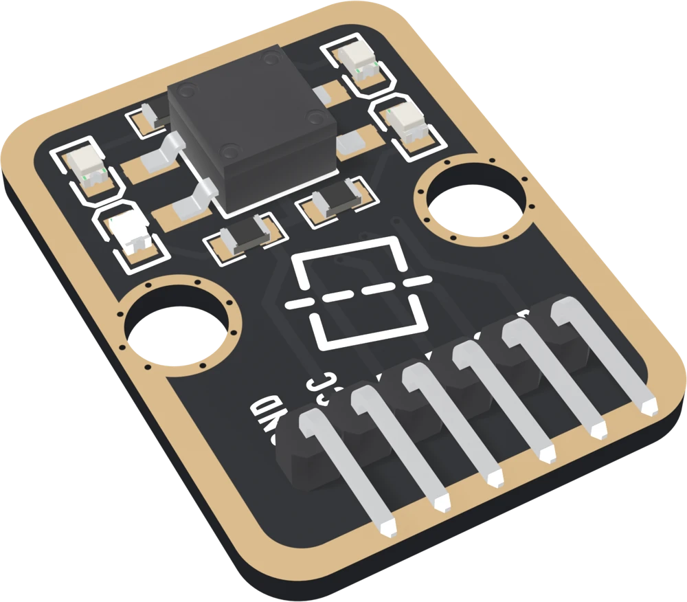
The LED beside each leg belongs to that leg's line: the lower-left LED to A, upper-left to B, upper-right to C, lower-right to D. When a sketch lights the pair the roller is joining, the two LEDs on the low side light, which is the second build in this book.
When it does not work
They came from this block's old page, and they describe a different part. This switch is one roller in one cell with four corner contacts. The difference matters: one roller can only be on one side at a time, so two opposite sides can never read at once.
The switch maker's drawing does not say, and nobody has measured it for this book. Tip the board slowly and watch the serial monitor: that is the honest answer for your board.
Not two opposite sides, ever: the roller cannot be on both. Tipped towards a corner, the roller can come to rest against the single contact in that corner, which joins nothing, or on either neighbouring side. It never joins a diagonal pair such as A and C.
Yes, that is the roller. It is loose in its cell by design, which is how it follows gravity. The rattle also shows up in the readings when the board is carried or knocked, and a knock is not a tilt covers the filter.
Why no pin reads LOW on its own, and how a sketch finds the pair the roller is joining.
No line goes to ground →Edit this page — content/books/four-direction-tilt-sensor/a-roller-and-four-corners.mdx
Questions about this product
See what other owners have asked, and read their solutions.
4-Direction Tilt Sensor
Loading discussions…
Discuss this article
Ask about this page. The answer stays here, on the page it belongs to, for whoever hits the same wall next.