The board, pin by pin
Four pins on one end, four bare holes on the other carrying the same four signals, and everything else hidden under the display. What each one is for, and why the back of the board is empty.
Four pins, in this order
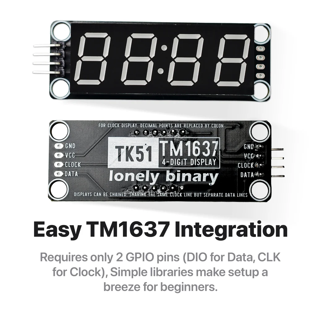
GND and VCC are power. CLOCK and DATA are the two signal wires from the last article. The library calls them CLK and DIO, the chip's datasheet calls them CLK and DIO, and the silkscreen calls them CLOCK and DATA — same wires, three habits.
Only the order matters, and the order is the same at both ends of the board.
What is under the display
Everything. The TM1637 is a surface-mount chip sitting on the display side, in the gap under the display's body, with two 10 kΩ resistors and two capacitors beside it.
The resistors are the pull-ups that hold CLOCK and DATA high, and they go to VCC. That is the single most consequential fact on this board: the voltage you feed VCC is the voltage those two wires will sit at, and therefore the voltage your board's pins will see. 3.3 V or 5 V is about nothing else.
The capacitors are across the supply. A multiplexed display takes its current in bursts — one digit's worth, forty times a millisecond — and the capacitors are what stop those bursts from appearing as dips on everything else sharing the supply.
The holes at the other end
The four plated holes at the far end are the same four nets as the header: GND, VCC, CLOCK, DATA. Not a pass-through to a second address — there is no such thing here — just the same wires, brought out again.
They are genuinely useful for passing power and clock along a row of displays. They are also the reason people accidentally build a row of displays that all show the same number, which more than one display goes through.
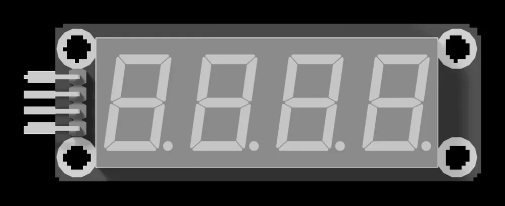
The enclosure in the box wraps the board and leaves the pins out of one end; the smoked film goes between the display and the window, and the only thing it does is make unlit segments disappear into the black instead of showing as grey bars.
When it does not work
Correct. The chip is a surface-mount part on the display side, underneath the display itself, along with the two resistors and the two capacitors. The back carries the silkscreen and the model number and nothing else.
The end with the pins. The four holes at the other end are the same four signals brought out again, so either end works electrically — but only one has a header soldered to it, and fitting one to the other end means soldering.
Solder a 4-pin header into the spare holes and use that end instead. The order is identical, GND first, because the two connectors are wired in parallel to the same four nets.
Mounting. They are 4.6 mm and sit 56 mm apart along the board and 16 mm across it, which is the grid the enclosure and the TinkerBlock base plate use. They are not electrical — nothing is connected to them.
Four wires, one library and a sketch that puts 1234 on the display.
The first number →Edit this page — content/books/tm1637-display/the-board-pin-by-pin.mdx
Questions about this product
See what other owners have asked, and read their solutions.
This page covers several products. Choose yours to see the right discussions.
Discuss this article
Ask about this page. The answer stays here, on the page it belongs to, for whoever hits the same wall next.