What is where
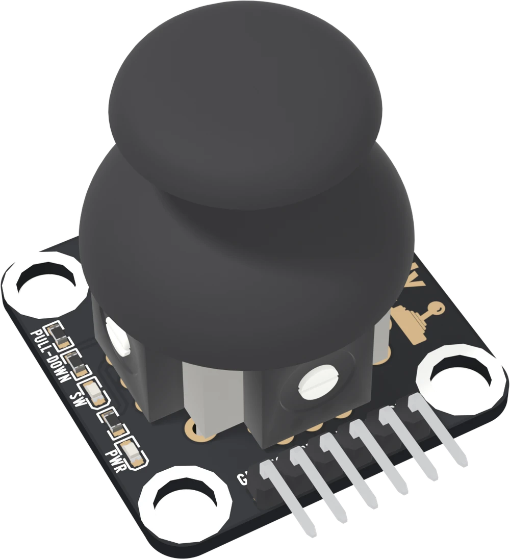
A square board 31.0 mm on each side, not the usual TinkerBlock size, with the thumbstick in the middle and its cap standing about 29 mm tall. Under the cap, two potentiometers and a switch. Up the left edge, the pull-down and two lights, PWR and SW.
A square board
The TK23 is 31.0 mm on each side, square, with a mounting hole in each corner. The holes are 4.8 mm across and their centres are 24 mm apart both ways. Almost everything else is the stick.
Under the cap
Pick a part and the figure rings it, with the cap see-through when the part is under it. The stick sits on a 16 mm square frame. A potentiometer on the frame's left side gives X, one along its bottom gives Y, and a push switch on the side away from the header is what the stick presses when you push it straight down.
Up the left edge, from the top: R10, the pull-down on SW, printed PULL-DOWN; R9 and the blue light printed SW; R1 and the red light printed PWR. The PWR light is on whenever the board has power. The SW light is on while the stick is pressed, and dim on a 3.3 V board. Both work without a sketch, which makes them the first thing to look at when a reading seems wrong.
Height
The supplier's drawing puts the bare stick 19.6 mm above the board and the frame 11.9 mm. The cap sits on top of that: in the 3D model its top is about 29 mm above the board and it is about 25 mm across. The header and the small parts are far lower, so the cap is the number that decides a lid or a panel.
When it does not work
It is square, 31.0 × 31.0 mm, where most TinkerBlocks are 22.4 × 30.4 mm, and its four mounting holes are 24 mm apart both ways. Check the spacing before you drill a panel, and leave room above the board for the cap.
Cut a round hole on the stick's axis, which is almost the middle of the board. The cap is about 25 mm across in the 3D model, so a hole for the cap is larger than a hole for the bare stick; the mechanical drawing on the reference page has the numbers.
Both are in the column of small parts up the left edge. The one printed PWR, nearer the header, is the power light, red. The one printed SW, in the middle of the column, is the click light, blue. The top two parts are the pull-down and the SW light's resistor.
What X and Y are: two dividers from VCC to GND, and where they rest.
Two pots in one stick →Edit this page — content/books/dual-axis-joystick/what-is-where.mdx
Questions about this product
See what other owners have asked, and read their solutions.
Dual Axis Joystick
Loading discussions…
Discuss this article
Ask about this page. The answer stays here, on the page it belongs to, for whoever hits the same wall next.