The 120 Ω resistor
Every TK109 ships with a 120 Ω resistor across CANH and CANL, and on a CAN bus it has two jobs: it absorbs the signal at the end of the cable, and it is what pulls the bus back to recessive, because nothing drives a 1. Two resistors, at the two ends, is right. Six boards straight from the box put six on the bus.
Job one: the end of the cable
An edge travels down a cable at roughly two thirds of the speed of light and, at an open end, reflects back. A resistor equal to the cable's own impedance, about 120 Ω for twisted pair, absorbs it instead. Either end's board may be talking, so both ends need one. This part is the same as on RS485.
Job two: getting back to 1
This part is CAN's own. A 0 is driven; a 1 is not. When a board stops driving, the bus has to fall back to recessive by itself, and it can only do that through whatever sits across CANH and CANL. The cable holds a little charge, like a small capacitor, and the resistors drain it.
With a 120 Ω at each end, 60 Ω drains it in a few tens of nanoseconds. With none, only the receivers' inputs are left, tens of kilohms, and on a few metres of cable the bus takes longer than a bit to get back. Recessive bits then read as dominant, and every frame fails. So on CAN, no terminators at all is not a long-cable problem. It can stop a bus on the desk.
Too many
The opposite fails more quietly. Every resistor left on sits across the pair, so six are 20 Ω. The driver is specified into 60 Ω; into 20 it makes a smaller difference and runs hotter. It usually still works on a short bus, and fails on a long, noisy one.
Which boards keep it
The two at the ends of the cable, and none between. On the TK109 it is the small resistor between the three bus pins and the chip, printed 121.
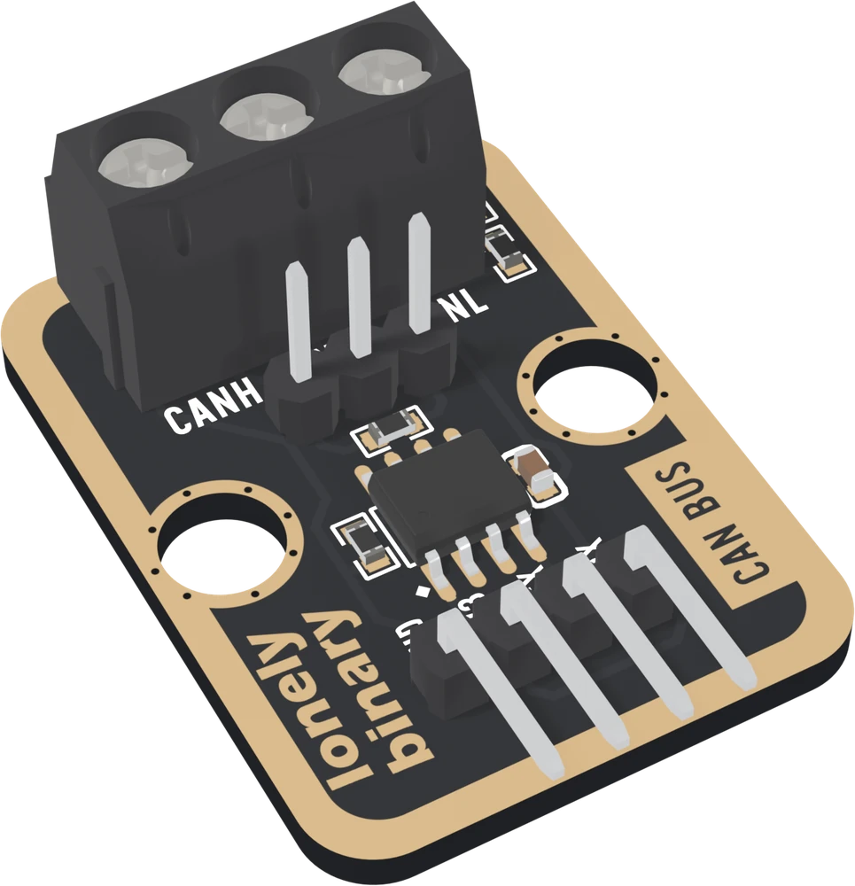
To take it off, heat one end with a little fresh solder on the iron and push it off its pad, then the other end. Then check: CANH to CANL on that board should read tens of kilohms. If a board later becomes an end, a through-hole 120 Ω in its screw terminal, between CANH and CANL, does the same job.
When it does not work
No. Two boards are the two ends of their cable, so both keep their 120 Ω, which makes the 60 Ω the standard asks for. That is how the first build in this book is wired.
On CAN that is expected. Recessive is not driven: the bus falls back only through whatever sits across the pair. With no resistor, only the receivers' own inputs are there, tens of kilohms, and the bus takes longer than a bit to return. Put a 120 Ω back at each end; a through-hole one in the screw terminal between CANH and CANL is fine.
It is the small resistor between the three bus pins and the chip, printed 121. Heat one end with a little fresh solder on the iron and push it off the pad, then the other end. Afterwards CANH to CANL on that board should read tens of kilohms, not 120 Ω.
On a desk it often does. Six resistors in parallel are 20 Ω, a third of the load the driver is built for, so it makes a smaller difference and more heat. On a long cable with noise on it, that lost margin is what fails first, and nothing on the bench explains it.
Why GND runs with CANH and CANL, and why the two are twisted together.
Ground and a twisted pair →Edit this page — content/books/can-bus/the-120-ohm-resistor.mdx
Questions about this product
See what other owners have asked, and read their solutions.
CAN Bus
Loading discussions…
Discuss this article
Ask about this page. The answer stays here, on the page it belongs to, for whoever hits the same wall next.