What is on the board
The TK103 is a PCM5102A DAC, a 3.5 mm stereo jack and a red power LED on a TinkerBlock board. Six pins go to the ESP32-S3: ground, 3.3 V, the two clocks, the data and XSMT, which a resistor on the board already holds HIGH. It is a 3.3 V board, and it comes in one box with the TK100 amplifier and the TK101 microphone.
One box, three blocks
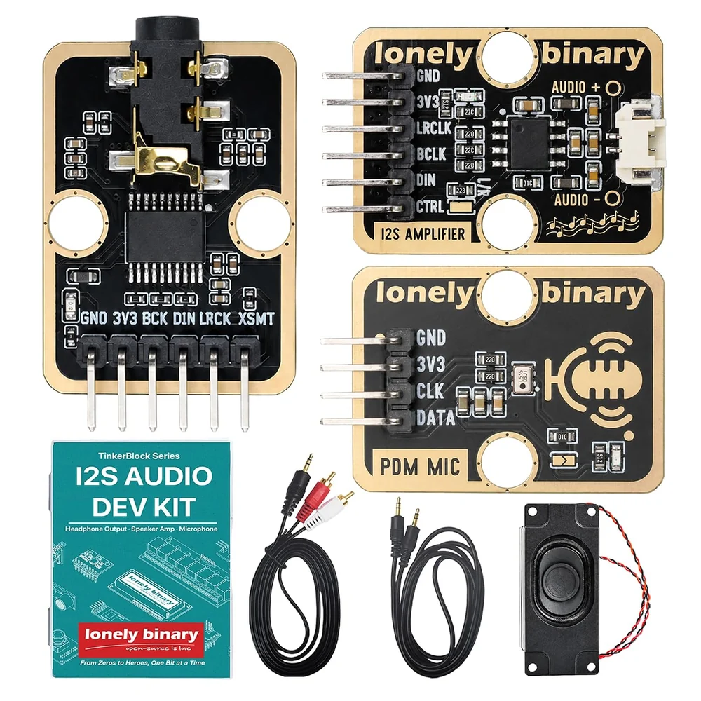
The kit holds the TK103 DAC, the TK100 amplifier, the TK101 PDM microphone, a 4 Ω 3 W speaker that plugs into the TK100, a 3.5 mm to 3.5 mm cable and a 3.5 mm to RCA cable. The ESP32-S3 and the jumper wires are not in the box.
Six pins to the ESP32-S3
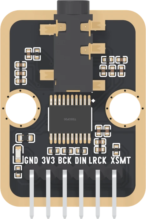
| Pin | The chip calls it | Wire it to |
|---|---|---|
| GND | AGND | GND |
| 3V3 | AVDD, CPVDD, DVDD | 3V3, never 5 V |
| BCK | BCK, bit clock | GPIO 42 |
| DIN | DIN, data | GPIO 41 |
| LRCK | LRCK, left/right clock | GPIO 40 |
| XSMT | XSMT, soft mute | GPIO 39, or nothing |
The GPIOs are the ones every sketch in this book uses. They leave the TK101's and the TK100's pins free, so any two blocks of the kit can be wired at once.
Everything on the header is an input to the board. The ESP32-S3 makes both clocks and the data; the TK103 only listens. BCK, DIN and LRCK each pass a 22 Ω resistor on the way to the chip, which softens the edges of fast clocks on a jumper wire.
XSMT is already HIGH
XSMT is wired straight to the chip and to a 10 kΩ resistor up to 3V3. With nothing connected it reads HIGH, which means play. A sketch may drive it LOW to mute, and XSMT: a mute that ramps shows what that does, but it never has to.
A 3.3 V board
The PCM5102A runs from 3.0 to 3.6 V, with an absolute maximum of 3.9 V, and the supply pin is printed 3V3. It draws about 20 mA, typical.
The red LED is lit from 3V3 through 5.1 kΩ. It says the board has power and nothing about sound.
When it does not work
No. The PCM5102A runs from 3.0 to 3.6 V and its absolute maximum is 3.9 V, so 5 V on the 3V3 pin is past the limit. The supply pin is printed 3V3: take it from the ESP32-S3's 3V3 pin.
No. A 10 kΩ resistor on the board pulls it up to 3V3, and HIGH means play. Connect it only if you want the sketch to mute the output: driving it LOW ramps the sound down.
Yes. The ESP32-S3 routes I2S through its GPIO matrix, so any free GPIO works: change the numbers at the top of the sketch. Avoid the strapping pins 0, 3, 45 and 46, the USB pins 19 and 20, and 35 to 37 on boards with octal PSRAM.
The LED only says the board has power. Check the three signal wires against the pin numbers in the sketch, then work through When it stays silent.
How the chip makes its own clock from BCK, and the one setting that stops it.
Three wires, no master clock →Edit this page — content/books/i2s-dac/whats-on-the-board.mdx
Questions about this product
See what other owners have asked, and read their solutions.
I2S DAC
Loading discussions…
Discuss this article
Ask about this page. The answer stays here, on the page it belongs to, for whoever hits the same wall next.