The four pins
Four pins, all four wired. GND is the square pad, VCC goes to your board's logic supply, and SDA and SCL are the two wires of an I2C bus. There is no light on this board: the only sign it is alive is the chip answering at 0x50.
What is on the board
One memory chip, four small parts beside it, and a four-pin header along the bottom edge. The header is right-angled, so the pins point out past the edge of the board and it lies flat in a breadboard or on a cable.
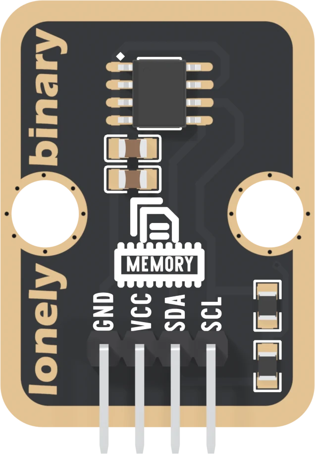
The chip keeps 16,384 bytes with the power off. A sketch writes a setting, the board is unplugged, and a week later the setting is still there. That is the whole job, and it takes two signal wires.
The four names
GND is on the square pad. Count from it.
VCC powers the chip, and it is also where the two pull-up resistors end. So VCC decides the voltage on SDA and SCL. Wire it to the voltage your board's pins run at: 5V on an Uno, 3V3 on an ESP32, an ESP32-S3 or a Pico. VCC sets the bus is the reason.
SDA is serial data and SCL is serial clock: the two wires of an I2C bus, the same two wires a temperature sensor or a display on I2C uses. Your board drives the clock; data goes both ways on SDA.
Every pin is wired. Unlike most TinkerBlock blocks, this one has no NC.
The back of the board
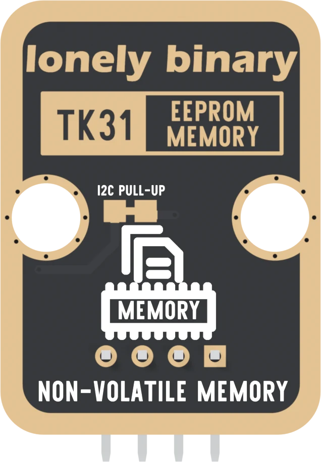
Turned over, the order reverses: the square pad is on the right. The back prints TK31, the number on the box, but no pin names. The two gold pads under I2C PULL-UP are joined by a thin strip of copper, and that strip is the subject of the pull-up jumper. Leave it alone for now.
When it does not work
Hold the board with the parts facing you and the header pins pointing down. Read GND, VCC, SDA, SCL from left to right. GND is also the square pad, which is the one mark that survives when the labels are hidden in a breadboard.
Nothing is meant to. The TK31 has no power LED. Run the I2C scan from the troubleshooting article: if it lists 0x50, the board is powered and wired, whatever it looks like.
On an Uno, no: I2C is A4 and A5 and nowhere else. An ESP32, an ESP32-S3 or a Pico can move I2C to other pins, but this book uses each board's default pins so that Wire.begin() needs no arguments.
Nothing is damaged. The chip simply never sees a valid start, and the scan finds nothing at 0x50. Swap the two wires back.
Edit this page — content/books/eeprom-memory/the-four-pins.mdx
Questions about this product
See what other owners have asked, and read their solutions.
EEPROM Memory
Loading discussions…
Discuss this article
Ask about this page. The answer stays here, on the page it belongs to, for whoever hits the same wall next.