What is on the board
The TK109 is a CAN transceiver: it turns your microcontroller's CAN controller into CANH and CANL and back. It brings no controller of its own, so it works with an ESP32, which has one built in, and not on its own with an Arduino Uno. Four pins go to the microcontroller, straight across, and three to the bus.
Six boards
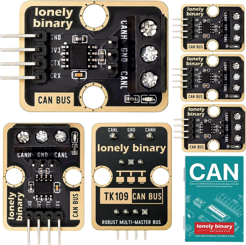
Each board is an SN65HVD230 CAN transceiver on a TinkerBlock board, 22.4 × 30.4 mm, with a 120 Ω resistor across the bus, a red power LED, and both headers soldered.
Four pins to your microcontroller
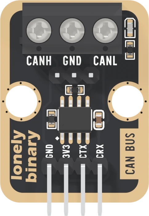
| Pin | The chip calls it | Wire it to |
|---|---|---|
| GND | GND | GND |
| 3V3 | VCC | 3V3, never 5 V |
| CTX | D, driver input | Your CAN TX pin |
| CRX | R, receiver output | Your CAN RX pin |
CTX and CRX are named from the microcontroller's side, so they go straight across: TX to TX, RX to RX. That is the opposite of most UART modules, and the first thing to check when nothing works.
The chip runs from 3.0 to 3.6 V, and its CTX and CRX pins take no more than 0.5 V above its own supply. This is a 3.3 V board.
Three to the bus
CANH, GND, CANL, on the screw terminal and again on the three pins below it: the same three nets either way. CANH goes to CANH on every other board, CANL to CANL, and GND to GND. Ground and a twisted pair explains why GND comes too.
What it does not bring
CAN takes two parts: a controller, which builds frames, arbitrates, answers other boards and counts errors, and a transceiver, which turns the controller's logic into CANH and CANL. This block is the transceiver.
Every ESP32 has the controller built in (Espressif calls it TWAI) and can put it on any two free GPIOs, which makes an ESP32 the natural partner. The builds in this book use two ESP32-S3 boards.
When it does not work
Not on its own. The Uno's ATmega328P has no CAN controller, and its 5 V pins would drive this board's 3.3 V inputs past their limit. A 5 V board needs a CAN controller chip such as the MCP2515, and 3.3 V logic between it and this block. An ESP32 has the controller built in.
No. These pins are named from the microcontroller's side: CTX goes to the pin your sketch calls the CAN TX pin, CRX to the CAN RX pin. Straight across. It is the opposite of a UART module whose TX goes to your RX.
The chip's absolute limit on its supply is 6 V, so it has probably survived. Its CRX output then swings to 5 V, which a 3.3 V microcontroller's pin is not built to take. Move the supply to 3V3 and check the microcontroller's RX pin still works.
Either: they are the same three nets, CANH, GND and CANL. The three pins suit jumper wires on a bench; the screw terminal suits stripped cable once the board is installed. Use one at a time for each wire.
Edit this page — content/books/can-bus/whats-on-the-board.mdx
Questions about this product
See what other owners have asked, and read their solutions.
CAN Bus
Loading discussions…
Discuss this article
Ask about this page. The answer stays here, on the page it belongs to, for whoever hits the same wall next.