What is on the board
The TK100 is an NS4168 amplifier on a TinkerBlock board: six pins to the ESP32-S3 along the bottom, a white speaker socket at the top, a solder jumper marked L/R and a red power LED. It comes in the I2S audio kit with a TK101 microphone, a TK103 DAC and a 4 Ω speaker.
One kit, three blocks
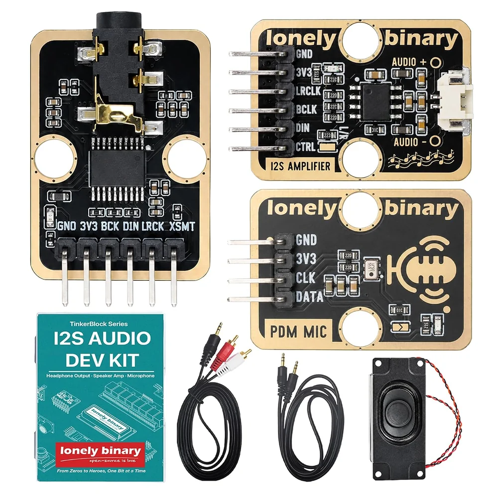
The TK100 comes in one box with two other blocks: the TK101 microphone and the TK103 DAC, plus a 4 Ω 3 W speaker that plugs into the TK100 and two 3.5 mm cables for the TK103. Headers come soldered. The ESP32-S3 and jumper wires are not in the box.
Six pins, one socket
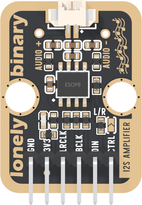
| Pin | Goes to | In this book |
|---|---|---|
| GND | GND | GND |
| 3V3 | the chip's supply, through a ferrite bead | 3V3, never 5 V |
| LRCLK | chip pin 2, through 22 Ω | GPIO 16 |
| BCLK | chip pin 3, through 22 Ω | GPIO 15 |
| DIN | chip pin 4, through 22 Ω | GPIO 17 |
| CTRL | chip pin 1, through 22 kΩ | GPIO 18, driven HIGH |
The 22 Ω in each I2S line softens the clock edges, and a ferrite bead in the supply keeps the amplifier's switching out of the rest of the circuit. Neither needs anything from you.
A tour
The speaker socket is a white two-pin socket with 1.25 mm pitch, between the labels AUDIO + and AUDIO -. Neither wire is ground, which Both wires move explains.
The L/R jumper is two half pads next to CTRL. It ships open, and it only matters when two TK100s share the same three wires to make stereo. CTRL: on, off, left or right works out what it does.
The power LED is red and lights whenever 3.3 V arrives. It is not a sign that the chip is on.
When it does not work
The LED is wired to 3V3 and lights whenever the board has power. It says nothing about the chip, which stays off until CTRL is driven HIGH. Check CTRL first.
Either way plays. Neither speaker wire is ground, so there is no wrong way for a single speaker. What matters is that nothing else touches either wire: not GND, not another board.
No. The header comes soldered and the kit's speaker plugs into the socket. The L/R solder jumper ships open, which plays the right channel, and the book's sketches play on either setting.
Yes, a bare speaker of 4 or 8 Ω, on a plug that fits the 1.25 mm two-pin socket. Something rated for about 1 W or more is comfortable on 3.3 V.
What LRCLK, BCLK and DIN carry, and why the chip plays only one channel.
Three wires, one channel →Edit this page — content/books/i2s-amplifier/whats-on-the-board.mdx
Questions about this product
See what other owners have asked, and read their solutions.
I2S Amplifier
Loading discussions…
Discuss this article
Ask about this page. The answer stays here, on the page it belongs to, for whoever hits the same wall next.