What is on the board
The TK101 is a LinkMems LMD2718T261-OA1 MEMS microphone on a TinkerBlock board, with a 22 Ω resistor in each signal line, a filter on its supply, a red power LED and a jumper. Four pins: GND, 3V3, CLK in and DATA out. It comes in the I2S audio kit with an amplifier block and a DAC block.
One kit, three blocks
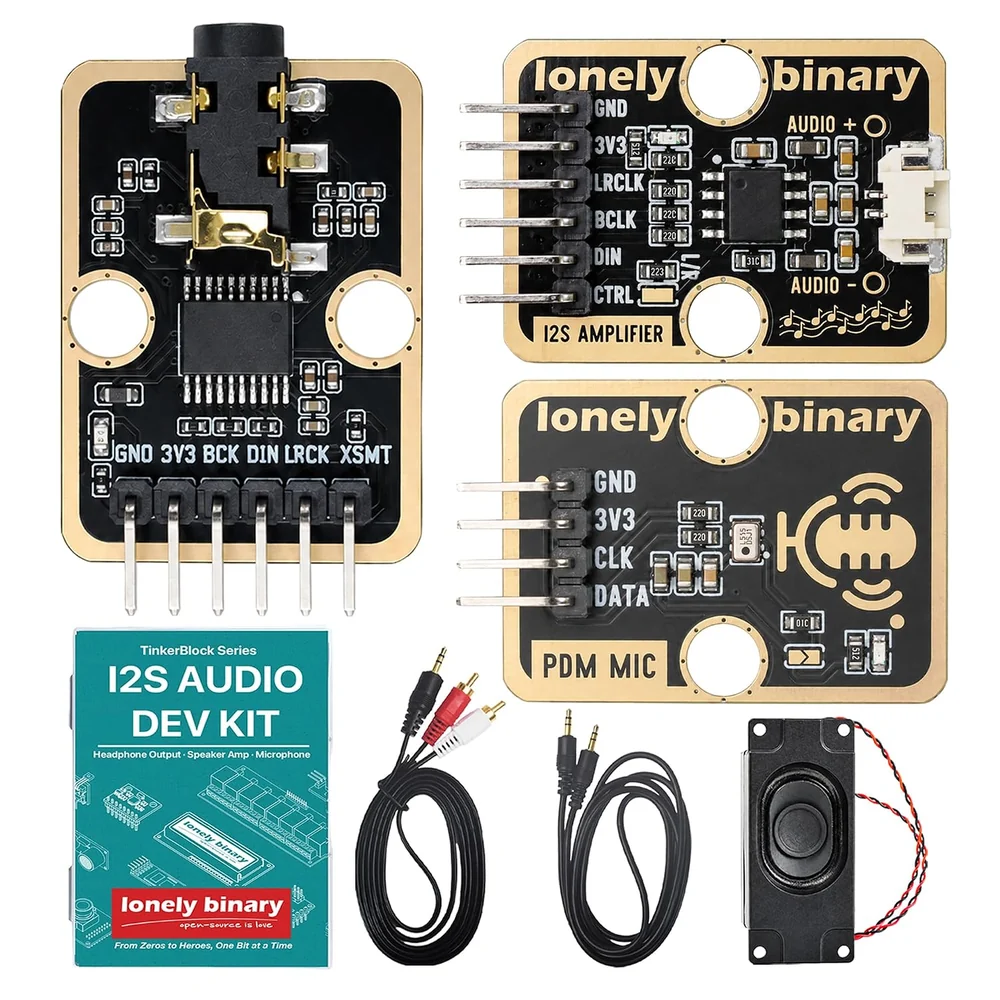
The TK101 comes in one kit with the TK100 amplifier, which drives the speaker, and the TK103 DAC, which feeds headphones. Every block's header is soldered. The ESP32-S3 and jumper wires are not in the box.
Four pins
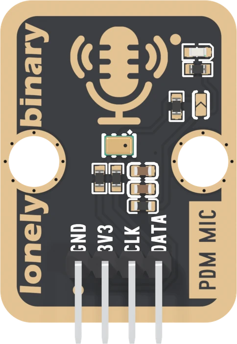
| Pin | Goes to | Wire it to |
|---|---|---|
| GND | ground | GND |
| 3V3 | the microphone's supply, through a filter | 3V3, never 5 V |
| CLK | the microphone's clock input | GPIO 5 in this book |
| DATA | the microphone's data output | GPIO 6 in this book |
The microphone is rated from 1.62 to 3.6 V. This is a 3.3 V board: 5 V is over the microphone's maximum.
What is between the pins and the microphone
- A 22 Ω resistor in CLK and another in DATA. They soften the edges of a fast signal. They do not change what you wire.
- A ferrite bead and two capacitors, 100 nF and 10 µF, between 3V3 and the microphone, so noise from the ESP32-S3's supply stays out of it.
- A 10 kΩ resistor and an open jumper on L/R. They set how the microphone shares its wire with a second one; Two microphones, one wire covers it. With one microphone, leave the jumper alone.
- A red LED on 3V3. It lights whenever the board has power, and says nothing about sound.
The microphone itself is a MEMS part: a tiny membrane and the electronics that turn its movement into bits, sealed in a can 2.75 × 1.85 mm with one 0.5 mm hole in the lid for the sound.
When it does not work
No. The microphone is rated from 1.62 to 3.6 V, so 5 V is over its maximum, and every header pin is printed 3V3. Wire 3V3 to the ESP32-S3's 3V3 pin.
The LED only says the board has power: it sits on 3V3 through 5.1 kΩ and has nothing to do with the microphone. Check that CLK and DATA reach the GPIOs the sketch names, 5 and 6 in this book, and that the sketch has started the PDM input.
Almost any free GPIO: the ESP32-S3 routes I2S through its GPIO matrix. Avoid the strapping pins 0, 3, 45 and 46, the USB pins 19 and 20, and 35 to 37 on boards with octal PSRAM. This book uses 5 and 6 so the microphone can sit beside the amplifier or the DAC.
The small rectangular metal can in the middle, under 3 mm long, below the gold microphone drawing. Its sound port is the tiny hole in the can's lid, on the front of the board.
How the ESP32-S3 turns a megahertz of bits into sixteen thousand numbers a second.
From bits to samples →Edit this page — content/books/pdm-microphone/whats-on-the-board.mdx
Questions about this product
See what other owners have asked, and read their solutions.
PDM Microphone
Loading discussions…
Discuss this article
Ask about this page. The answer stays here, on the page it belongs to, for whoever hits the same wall next.