What is on it
A GK105A slot sensor with an infrared LED in one tower and a light sensor in the other, an LM393 comparator that turns the sensor's voltage into HIGH or LOW, four 10 kΩ and two 1 kΩ resistors, a capacitor and a red LED. The infrared LED is always on, so the block draws a few milliamps whenever it has power.
The two black towers
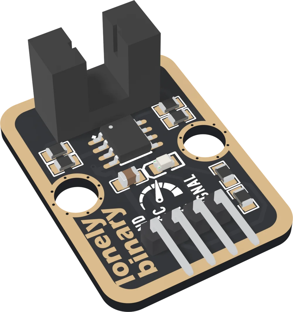
The towers are one part, a GK105A slotted optical switch: 12.9 × 6.3 mm and 11 mm tall, with a slot 5 mm wide and 8 mm deep between them. The right-hand tower holds an infrared LED. The left-hand one holds a phototransistor, a light sensor that passes current while light reaches it. They face each other through small windows across the slot.
Pick each part. Below the slot sensor:
- U5, an LM393 comparator. It compares the light sensor's voltage with a fixed one and answers on SIGNAL. It holds two comparators; this board uses one.
- R12 and R13, 10 kΩ each, make that fixed voltage: half of VCC.
- R10, 1 kΩ, feeds the infrared LED. R11, 10 kΩ, is the light sensor's load, and it also sets how fast the block can count.
- R7, 10 kΩ, pulls SIGNAL up to VCC. R9, 1 kΩ, and the red LED run from VCC onto SIGNAL, so the LED lights while SIGNAL is LOW.
- C3, 100 nF, steadies the supply at the comparator.
Never off
The infrared LED is on whenever the block has power, blocked or not: about 2.2 mA from 3.3 V and 3.9 mA from 5 V. With the comparator, the divider and, while the slot is clear, the red LED and the pull-ups, the whole block takes about 3 to 5 mA from 3.3 V and 5 to 8 mA from 5 V. That is worked out from the parts' typical voltages, not measured, and it matters only on a battery.
The part is marked GK105A; the BOM orders it from Everlight, whose own sheet for it could not be found. This book quotes SIVAGO's GK105A sheet, a part of the same name and package, and says so where a number depends on it.
When it does not work
The beam is infrared, which eyes cannot see. A phone camera often can: point it into the slot from the end and look for a faint purple glow on the right-hand tower. Some phones filter infrared on the main camera; the front camera usually shows it better.
The light sensor gives a voltage that slides as an edge crosses the beam. The comparator turns that slide into a clean HIGH or LOW at one point, half of VCC, with a fast edge a microcontroller can count. The block does the deciding so your sketch does not have to.
No. The line the comparator judges by is fixed at half of VCC by two equal 10 kΩ resistors. A slot sensor does not need one: the beam is either through the slot or not.
Edit this page — content/books/ir-speed-sensor/what-is-on-it.mdx
Questions about this product
See what other owners have asked, and read their solutions.
Infrared Speed Sensor
Loading discussions…
Discuss this article
Ask about this page. The answer stays here, on the page it belongs to, for whoever hits the same wall next.