The six pins
Six pins, five of them wired. GND and VCC power the chip and the digit, LATCH, CLOCK and DATA are the three wires that set all eight segments, and NC is connected to nothing. The pins are numbered on the board, and this block has no square pad, so the numbers are what you count from.
What it is
One digit, driven by three wires. The TK53 carries a 0.8-inch red seven-segment digit and, under it, a 74HC595 shift register. Your board sends a byte down DATA, one bit per pulse on CLOCK, then pulses LATCH, and the eight bits appear on the seven segments and the dot all at once.
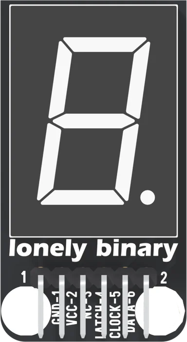
The header is right-angled and its pins lie flat over the bottom of the board, ending just inside the edge, so a cable plugs on from below.
The six names
GND is pin 1. The digit's common pins are on it, so every lit segment's current comes home this way.
VCC is pin 2. It powers the 74HC595, and every lit segment's current starts here. It also decides what the chip counts as HIGH, which is why it goes to your board's logic supply: 5V on an Uno, 3V3 on an ESP32, an ESP32-S3 or a Pico. VCC sets the current has the numbers.
NC is pin 3, not connected. Leave it empty.
LATCH, CLOCK and DATA are pins 4, 5 and 6: the three wires your board drives. Shift, then latch is how they work together.
The back
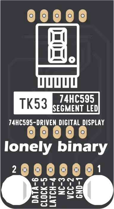
The back prints the same six names, mirrored: DATA-6 on the left and GND-1 on the right. Most TinkerBlock boards mark pin 1 with a square pad. This one does not: all six pads are the same rounded shape, so the printed numbers are the only mark. The ten pads above them are the digit's own legs.
When it does not work
Hold the board with the digit facing you and the header at the bottom. GND is the left-hand pin, printed GND-1, and the rest follow in order to DATA-6 on the right. There is no square pad on this block, so read the printed numbers.
No. NC is soldered to a pad that no trace on the board reaches. It is there so every TinkerBlock header has the same shape. A wire on it does no harm and no good.
Nothing is meant to until a sketch sends a byte. The block has no power LED, and the datasheet does not say what the 74HC595 holds at power-up, so the digit may be dark or show a few stray segments. Run the counting sketch.
Any three digital outputs will do: they are ordinary pins, not a bus with fixed pins. The book uses D8, D12 and D11 on an Uno, and pins that are free at boot on the others. On an ESP32, keep away from GPIO 6 to 11, which run the flash.
The chip, eight resistors and a capacitor, all hidden under the digit, and three chip pins wired in copper.
Under the digit →Edit this page — content/books/hc595-segment-led/the-six-pins.mdx
Questions about this product
See what other owners have asked, and read their solutions.
74HC595 Segment LED
Loading discussions…
Discuss this article
Ask about this page. The answer stays here, on the page it belongs to, for whoever hits the same wall next.