What is on it
Five parts and a header. An SW-520D tilt switch in a 12 mm brass can, a 10 kΩ that holds SIGNAL LOW while it is open, a 100 nF beside it, and a red LED with its 1 kΩ that lights whenever it is closed. Open, the block draws no current at all.
The can across the top
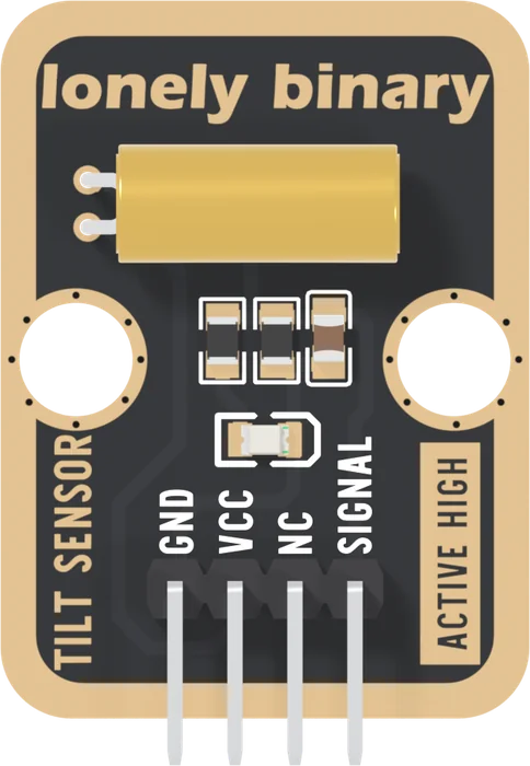
The brass can is the sensor. It is an SW-520D: 12 mm long and 5 mm across, with two steel balls loose inside and its two leads at one end. It lies flat on the board with the leads bent through 90 degrees into two pads at its left end. Which end has the leads is the one thing to remember about it: two balls in a can explains why.
Pick each part. Under the can are three 0805 parts in a row, and the LED below them:
- R7, 10 kΩ, from SIGNAL to GND: the pull-down. It gives SIGNAL a definite LOW while the switch is open.
- C2, 100 nF, from SIGNAL to GND beside it. It fills at once when the switch closes and takes about a millisecond to empty when it opens, so the shortest flickers of a rattling ball never reach your pin as LOW.
- R8, 1 kΩ, and the LED, also from SIGNAL to GND. With the switch closed the LED lights, about 1.3 mA from 3.3 V and 3 mA from 5 V (a red LED's usual 2 V drop, worked out, not measured).
Nothing draws current while it is open
VCC reaches one lead of the switch and nothing else. With the switch open there is no path from VCC anywhere, so the block takes no current at all. Closed, it takes what the pull-down and the LED need: about 1.6 mA at 3.3 V, well inside the 10 mA its maker rates the switch for. On a battery, mount it so the position it spends most of its time in is the open one.
When it does not work
Yes. The LED hangs off SIGNAL and is fed from VCC through the closed switch, so it lights whenever the left edge is down and the block has VCC and GND, whatever your board is doing. It is a switch light, not a power light.
Do not. The leads are soldered through the board and bent once already; bending them again near the can is how they crack. Turn the whole block instead: standing it on its left edge puts the can upright, lead end down.
The two balls inside the can are loose on purpose: rolling to the lower end is how the switch works. The rattle is them. A knock that lifts them off the contacts also shows on SIGNAL, which the rattle article deals with.
How rolling balls make a switch, and why level is not an answer.
Two balls in a can →Edit this page — content/books/tilt-sensor/what-is-on-it.mdx
Questions about this product
See what other owners have asked, and read their solutions.
Tilt Sensor
Loading discussions…
Discuss this article
Ask about this page. The answer stays here, on the page it belongs to, for whoever hits the same wall next.