Three volts only
3V3 goes straight to the panel, and so does every signal pin. The ST7735S's inputs are rated to their own supply plus 0.3 V, 3.6 V here, and count anything over 2.31 V as HIGH. An ESP32, an ESP32-S3 or a Pico wires straight across. An Uno's 5 V HIGH is 1.4 V too much: it goes through a TK97, as the back of the board says.
Nothing in between
Five of the eight pins go straight from the header to the panel's ribbon. There is no resistor, no level shifter and no regulator on the way. So the voltages your board puts on them are the voltages the controller gets.
The controller is a Sitronix ST7735S. Its data sheet runs its logic from 1.65 to 3.7 V, and here that supply is the board's 3V3. It reads anything over 0.7 of that, 2.31 V, as HIGH. And it allows no input to go more than 0.3 V over its supply: 3.6 V.
An ESP32, an ESP32-S3 and a Raspberry Pi Pico all drive their pins at 3.3 V: a clean HIGH, under the limit. They wire straight across, 3V3 to 3V3.
An Uno needs a TK97
An Arduino Uno drives its pins to 5 V. That is 1.4 V past the limit on every HIGH, and SCL alone goes HIGH millions of times a second. The back of the board says it in a box: use it with 3.3 V boards, and put a TK97 logic level converter between it and a 5 V Uno, to prevent damage, flickering or blurring.
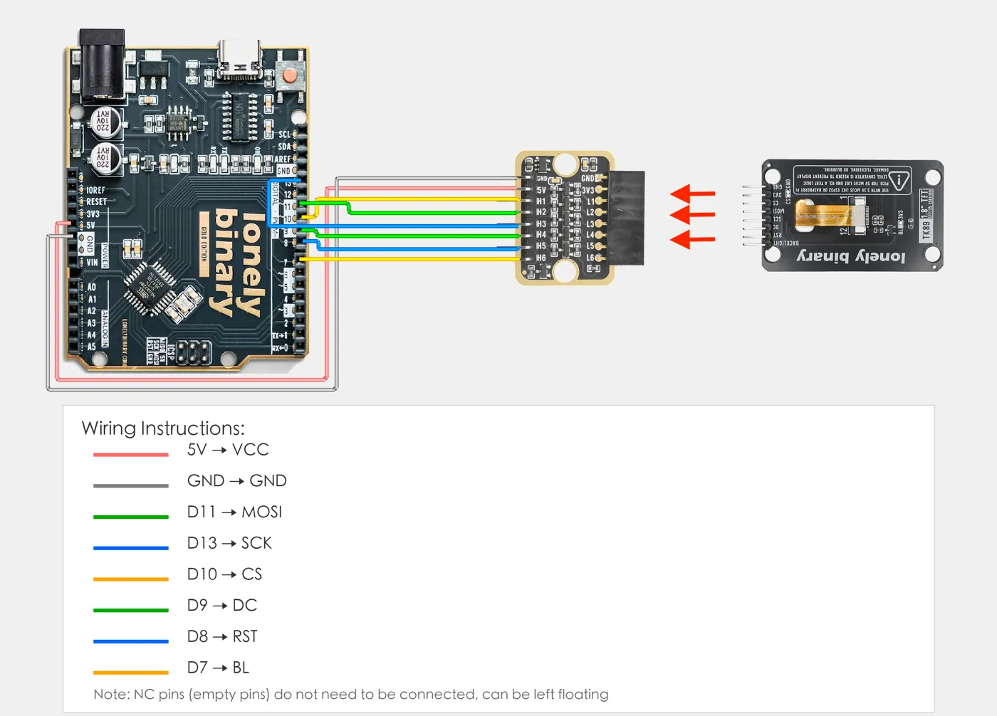
In the owner's diagram the TK89 plugs straight into the socket on the TK97's 3.3 V side, marked GND, 3V3 and L1 to L6. The Uno sends 5V, GND and its six signals into the other side.
Two things come with the converter. It rounds the edges of a fast clock, so if the picture is noisy through it, slow the SPI clock. And it is one more thing to wire wrongly: when an Uno build shows nothing, check the TK97's 5V and GND wires first.
When it does not work
No. Every HIGH puts 5 V on an input rated to 3.6 V, and nothing on the board is in between. It can work for a while, or flicker and smear, and the damage builds up. Put a TK97 between them.
No. 3V3 on this board goes straight to the panel's supplies and the backlight: there is no regulator. Feed it 3.3 V, from your board's 3V3 pin or the TK97's 3.3 V side.
Yes. Use 3V3. The ESP32's signals are already 3.3 V, so the only thing that could put 5 V on the display is the supply wire.
A level converter slows the fast edges of the SPI clock. Keep the wires short and slow the clock with tft.setSPISpeed(4000000) after initR(). If that cures it, the clock was too fast for the converter.
Why the screen is black until one pin goes HIGH, and how to dim it.
The backlight waits for BL →Edit this page — content/books/tft-1-8-inch/three-volts-only.mdx
Questions about this product
See what other owners have asked, and read their solutions.
1.8-inch TFT Display
Loading discussions…
Discuss this article
Ask about this page. The answer stays here, on the page it belongs to, for whoever hits the same wall next.