What is on it
One SS49E-type Hall chip in a three-legged SOT-23 package, a 100 nF capacitor across its supply and another from its output to GND. No resistor, no LED, no adjustment. The chip draws about 5 mA at 5 V all the time, and the output capacitor is a filter far too fast to hide anything a hand does.
One chip, two capacitors
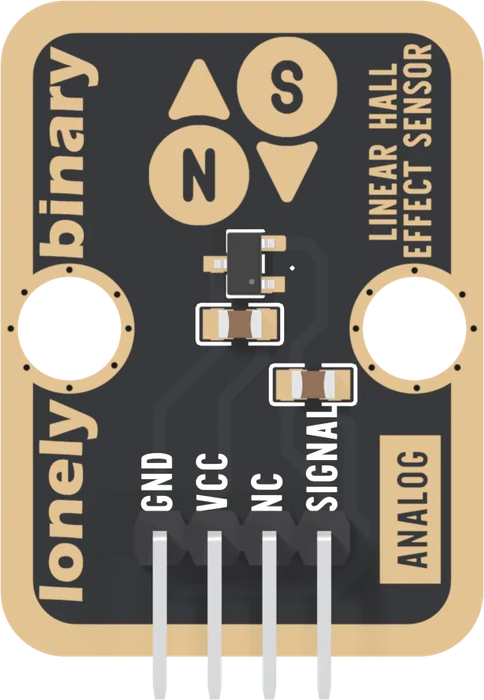
The chip is a Slkor SLSS49E, the SOT-23 version of a part the industry calls the SS49E. Inside it is a Hall element, a thin plate of semiconductor that makes a tiny voltage when a field passes through it, an amplifier and an output stage. Pin 1 is VCC, pin 2 GND, pin 3 the output. The data sheet runs it from 3 to 12 V.
It is on whenever VCC is: there is no sleep and no enable pin, and it draws 3 to 8 mA at 5 V, 5 mA typical. That matters on a battery and nowhere else.
What the capacitors do
C3 sits across the chip's supply. It holds VCC steady at the chip against its own current and against noise picked up along the cable, so the output does not jump when something else on the rail switches.
C4 runs from SIGNAL to GND. With the chip's output it is a low-pass filter. The sheet gives no output resistance; its load figures cap it at about 1.2 kΩ, which puts the corner at 1.3 kHz or higher. A magnet on a shaft at 3000 rpm passes 50 times a second, so nothing you do with a magnet is slowed by it. Its other job is for the ADC, which measures by charging a small capacitor of its own from the pin. 100 nF right at the pin hands over that charge without the voltage dipping.
There is no LED. Nothing on the board shows that it is powered or that a magnet is near; the reading is the only test.
When it does not work
The small black part with three legs, just under the N and S drawing. A magnet has to be over that, not over the header or the two brown capacitors. It senses the field passing through its face, front to back or back to front.
There is nothing on the board to adjust. It does need its zero measured, in software: the resting level varies from chip to chip by a tenth of a volt or more at 5 V. The first-reading sketch does it at start-up.
It draws about 5 mA at 5 V, typical, which is 25 mW: barely warm at most. Anything hot to the touch is not normal. Check VCC and GND are not swapped: the chip survives only half a volt reversed.
There is no need. With the chip's output it makes a filter whose corner is about 1.3 kHz or higher, far above anything a magnet moved by hand or a slow shaft does, and it steadies the pin for the ADC.
The straight line from field to voltage, and where it starts.
Half the supply at rest →Edit this page — content/books/linear-hall-sensor/what-is-on-it.mdx
Questions about this product
See what other owners have asked, and read their solutions.
Linear Hall Effect Sensor
Loading discussions…
Discuss this article
Ask about this page. The answer stays here, on the page it belongs to, for whoever hits the same wall next.