The four pins
Four pins, three of them wired: GND on the square pad, VCC to the two LEDs' resistors and nothing else, and SIGNAL through 1 kΩ into a transistor. NC is connected to nothing. SIGNAL HIGH turns the infrared LED on, which is what ACTIVE HIGH on the front says.
Three wires and a spare
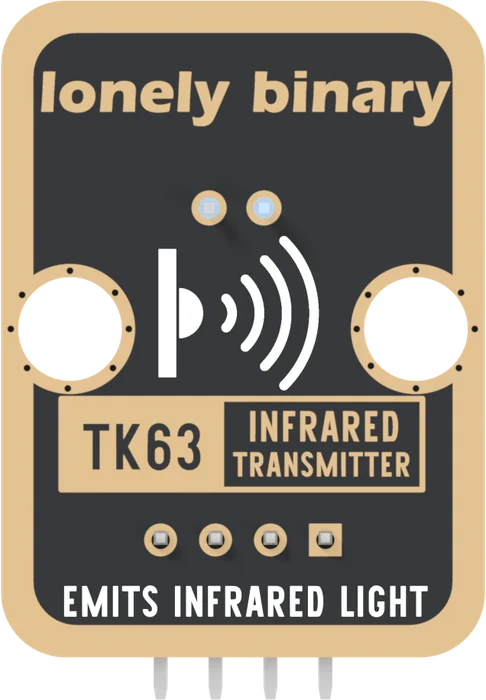
The header is four right-angle pins, 2.54 mm apart, printed GND, VCC, NC and SIGNAL from left to right with the parts facing you. GND is on the square pad, and that pad is the only way to tell four identical holes apart. Count from it.
Pick a pin to see where it goes. GND is the transistor's emitter, where every milliamp the LEDs take comes back. VCC reaches the two LEDs' resistors and nothing else. SIGNAL reaches one 1 kΩ resistor, which leads into the transistor's base. NC is in no net at all.
What HIGH means
The front prints ACTIVE HIGH up its right edge. SIGNAL HIGH turns the
transistor on, and both the infrared LED and the small red LED light.
SIGNAL LOW turns it off. There is no library and no chip: pinMode(pin, OUTPUT) and digitalWrite are the whole interface, until you want a
remote-control carrier.
VCC is yours to choose
On most blocks VCC must be your board's logic voltage, because it ends up on SIGNAL. Not on this one. VCC only feeds the LEDs, and the transistor keeps it away from your pin, so 5V is right even on a 3.3 V board, and it buys range. Five volts is allowed here says how much, and where the limit is.
When it does not work
The square pad. From the front, parts up and pins pointing down, it is the left-hand pin, and the order is GND, VCC, NC, SIGNAL. The back prints no pin names; turned over, the square pad is on the right and it is still GND.
No. It is soldered to a pad that no trace reaches, so it makes no difference either way. It is there so every TinkerBlock block has the same four-pin header and one cable fits all of them.
Yes. VCC feeds the two LEDs through their resistors and meets SIGNAL nowhere on the board, so your pin never sees it. 5V gives the infrared LED about 24 mA instead of 13 mA, and more reach.
The infrared LED, the transistor, one resistor that sets the current, and a red light.
What is on it →Edit this page — content/books/ir-transmitter/the-four-pins.mdx
Questions about this product
See what other owners have asked, and read their solutions.
Infrared Transmitter
Loading discussions…
Discuss this article
Ask about this page. The answer stays here, on the page it belongs to, for whoever hits the same wall next.