What is on it
Five parts and a header. A Vishay TCRT5000, an infrared emitter and a receiver in one black housing looking out of the front of the board; a 120 Ω that keeps the emitter lit whenever the block has power; a 4.7 kΩ pull-up on SIGNAL; and two 100 nF capacitors. No comparator, no potentiometer, no indicator LED.
A sensor that looks out of the front
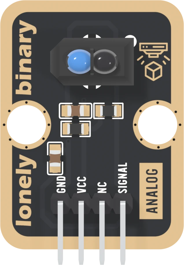
The black housing near the top is a Vishay TCRT5000, 10.2 × 5.8 mm and 7 mm tall. Inside it, side by side, are an infrared LED under the blue dome and a phototransistor under the black one, both looking the same way: straight out of the front of the board. The housing keeps the emitter's light from reaching the receiver sideways, so what the receiver sees is what comes back off a surface.
Pick each part. Around the sensor are four 0805 parts:
- R13, 120 Ω, from VCC to the emitter. Nothing else is in that path, so the emitter is lit whenever the block has power: about 17.5 mA at 3.3 V. Your sketch cannot switch it off.
- R10, 4.7 kΩ, from VCC to SIGNAL: the pull-up. The receiver hangs from it, so SIGNAL falls as more light comes back.
- C2 and C3, 100 nF. C2 steadies the emitter's supply. C3 runs from SIGNAL to GND and smooths the reading; with the 4.7 kΩ it sets how fast SIGNAL can climb, which matters when you count things going past quickly.
Always on, always drawing
The block takes about 18 mA from 3V3 all the time, nearly all of it in the emitter, whether anything is in front of the sensor or not. That is more than most TinkerBlock blocks, and on a battery it counts. The emitter never rests works through what it costs at 3.3 V and at 5 V.
When it does not work
Infrared at about 950 nm is invisible to the eye. Many phone cameras show it as a faint purple glow in the blue dome, though some filter it out. The sketch is the surer test: slide white paper under the sensor and the reading should drop.
The front, the side with the parts and the pin names. The sensor's two domes look straight out of it, so for a line follower the block hangs face down with the domes a few millimetres over the floor.
No, this board has none. It gives a voltage and nothing else; the only light on it is the infrared emitter, which is always on and invisible. Print the reading, or drive an LED block from your sketch.
How light that bounces back becomes a voltage that falls.
Light out, light back →Edit this page — content/books/reflective-optical-sensor/what-is-on-it.mdx
Questions about this product
See what other owners have asked, and read their solutions.
Reflective Optical Sensor
Loading discussions…
Discuss this article
Ask about this page. The answer stays here, on the page it belongs to, for whoever hits the same wall next.