The four pins
Four pins, three of them wired. GND is the square pad, VCC goes straight to the buzzer, SIGNAL reaches a transistor through 1 kΩ, and NC is connected to nothing. The buzzer only sounds while SIGNAL is a square wave; held HIGH it is silent.
The header
A buzzer, the parts that switch it, and a four-pin header along the bottom edge. The header is right-angled, so the pins point out past the edge of the board and it lies flat in a breadboard or on a cable.
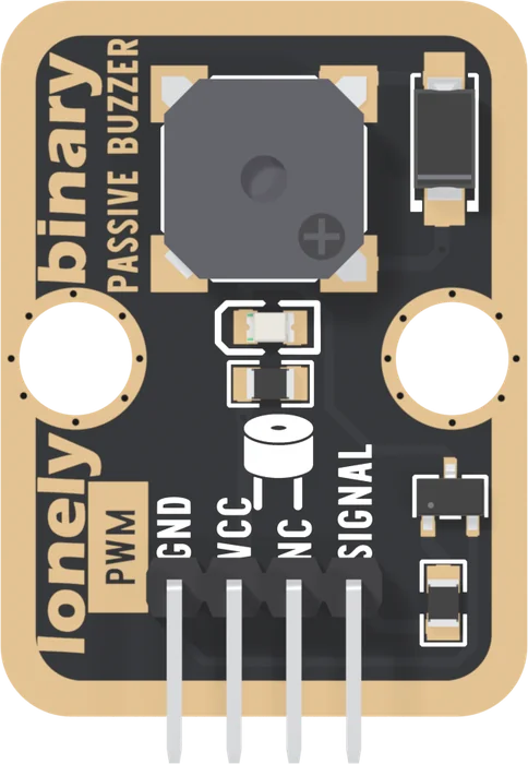
Read the four pins left to right with the parts facing you: GND, VCC, NC, SIGNAL. Three of them are wired.
GND and SIGNAL are the pair that matter to your sketch. SIGNAL is measured against GND, and the buzzer's current comes back through GND, so it has to be your board's own ground.
VCC is the buzzer's supply, straight to its + pad with no regulator in between. It never touches SIGNAL, which is why it can be 5V even beside a 3.3 V board. The choice between 3V3 and 5V is loudness against the buzzer's listed range; the first beep makes it.
What SIGNAL wants
Not a level: a wave. The front of the board prints PWM beside the header, and the back prints USE PWM SIGNAL TO MAKE SOUND. A square wave on SIGNAL is the sound, and its frequency is the pitch.
Held HIGH, this buzzer makes one click and goes silent, while the coil inside goes on drawing current. That is the difference between a passive buzzer and an active one, and it has its own article.
The back
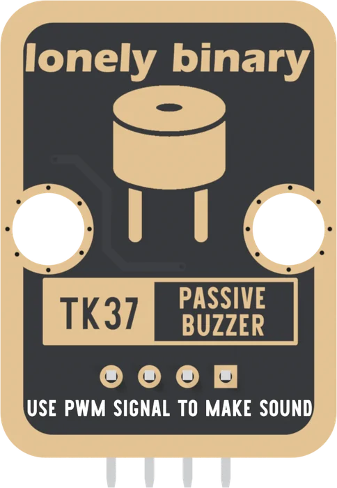
The drawing on the back is a generic round buzzer; the part fitted is the square one on the front.
When it does not work
Hold the board with the parts facing you and the header pins pointing down. Read GND, VCC, NC, SIGNAL from left to right. GND is also the square pad, the one mark that survives when the board is in a breadboard and the labels are hidden. Turned over, the square pad is on the right.
No. It is not connected to anything on the board. It is there so every TinkerBlock block has the same four-pin header. Wiring it does no harm and changes nothing.
Either is safe on any board, because VCC never reaches SIGNAL. 3V3 keeps the buzzer inside the 2.5 to 4.5 V its datasheet lists; 5V is a few decibels louder and is the voltage the maker tests it at. This book wires 3V3 on the ESP32-S3.
The back prints TK37 PASSIVE BUZZER and USE PWM SIGNAL TO MAKE SOUND, and nothing over the holes. Count from the square pad, which is GND on both faces.
Edit this page — content/books/passive-buzzer/the-four-pins.mdx
Questions about this product
See what other owners have asked, and read their solutions.
Passive Buzzer
Loading discussions…
Discuss this article
Ask about this page. The answer stays here, on the page it belongs to, for whoever hits the same wall next.