The six pins
Six pins, five of them wired. GND, VCC, CS, DIN, NC and CLK from the left with the matrix up. There is no square pad on this board, so count from GND, and the pin marked NC is connected to nothing at all.
What it is
Sixty-four red LEDs in one square package, and a chip under it that keeps a picture in its own memory and lights it for you. Your board sends the picture as eight bytes, once. After that the display looks after itself until the next picture arrives.
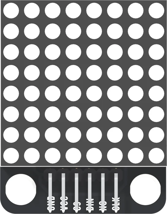
The header is right-angled: the pins lie flat over the board and end at its bottom edge, so it sits on a breadboard edge or takes a cable.
The six names
GND is the left-hand pin. On most TinkerBlock boards GND is also the square pad; on the TK52 all six pads are the same oval, so the printed name is the only mark. Count from it.
VCC feeds the chip and every LED. It goes to 5V, whatever voltage your board's own pins run at. 5 V on VCC, 3.5 V for a HIGH is the reason.
CS, DIN and CLK carry the picture: DIN the bits, CLK the moment each bit is read, and CS the moment a whole message takes effect. Sixteen bits and a latch follows one message down them.
NC means not connected, and here it means exactly that: no trace reaches it. It sits between DIN and CLK, so a wire meant for CLK that lands one pin to the left goes nowhere and the display stays dark.
The back
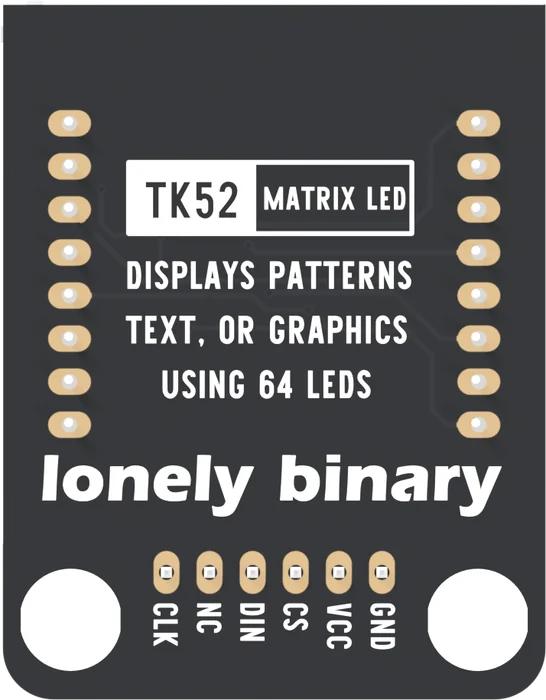
The two columns of eight pads are the matrix's sixteen legs. Everything else the board carries is on the front, under the matrix.
When it does not work
Hold the board with the matrix facing you and the header at the bottom. GND is the left-hand pin, and it is printed beside the pin on the front. Turned over, the back prints the same names mirrored, so GND is on the right.
No. The pad marked NC has a header pin soldered to it and no trace on the board reaches it. Wiring it to something does nothing, and leaving it empty does nothing. It keeps the six-pin order the same as the chainable module's.
Yes. The book's sketch drives all three by hand, so any three output pins work. It uses each board's hardware SPI pins so that the wiring still suits the SPI library if you move to it later.
There is none. The MAX7219 has a DOUT pin, and on this board it reaches no pad. That is why a TK52 cannot pass data on to a second matrix. The chainable module in the 3-pack is the one with an OUT edge.
The matrix, and the three parts it hides: the chip, the resistor that sets the current, and a capacitor.
What is on the board →Edit this page — content/books/matrix-led/the-six-pins.mdx
Questions about this product
See what other owners have asked, and read their solutions.
This page covers several products. Choose yours to see the right discussions.
Discuss this article
Ask about this page. The answer stays here, on the page it belongs to, for whoever hits the same wall next.