The four pins
Four pins, three of them wired: GND on the square pad, VCC to the emitter and the pull-up, and SIGNAL, which is a voltage and not a yes or no. NC is connected to nothing. The front prints ANALOG beside the header, and it means it: there is no threshold on this board.
Three wires and a spare
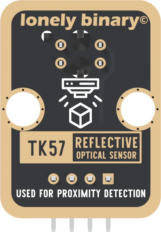
The header is four right-angle pins, 2.54 mm apart, printed GND, VCC, NC and SIGNAL from left to right with the parts facing you. GND is on the square pad, and that pad is the only way to tell four identical holes apart. Count from it.
Pick a pin to see where it goes. GND is where the emitter's current and the sensor's current both return. VCC feeds the emitter through 120 Ω and the pull-up that SIGNAL hangs from. SIGNAL is the sensor's output, with 4.7 kΩ up to VCC. NC is in no net at all.
What ANALOG means
The front prints ANALOG up its right edge. SIGNAL is a voltage anywhere between a few tenths of a volt and VCC, and the more infrared comes back from whatever is in front of the sensor, the lower it goes. White paper close up pulls it down to around a volt. Black tape, or nothing at all, leaves it near VCC.
There is no comparator, no potentiometer and no indicator LED on this board. Many TCRT5000 boards sold for line-following robots have all three and give a digital output. This one hands you the raw voltage, so the threshold is a number in your sketch, and you can move it.
VCC is your board's logic voltage
Over a dark surface SIGNAL rises all the way to VCC, so VCC decides the most voltage your pin will see. Wire it to the voltage your board's pins run at: 3V3 on an ESP32, an ESP32-S3 or a Pico, 5V on an Uno. VCC is your logic voltage shows why, board by board.
When it does not work
The square pad. From the front, parts up and pins pointing down, it is the left-hand pin, and the order is GND, VCC, NC, SIGNAL. The back prints no pin names; turned over, the square pad is on the right and it is still GND.
It will return something, because a digital pin decides HIGH or LOW at its own threshold. But that threshold is the chip's, not yours, and it sits wherever the chip puts it. Read it with analogRead and choose the threshold in the sketch, as the counter in this book does.
No. It is soldered to a pad that no trace reaches, so it makes no difference either way. It is there so every TinkerBlock block has the same four-pin header and one cable fits all of them.
Edit this page — content/books/reflective-optical-sensor/the-four-pins.mdx
Questions about this product
See what other owners have asked, and read their solutions.
Reflective Optical Sensor
Loading discussions…
Discuss this article
Ask about this page. The answer stays here, on the page it belongs to, for whoever hits the same wall next.