First light
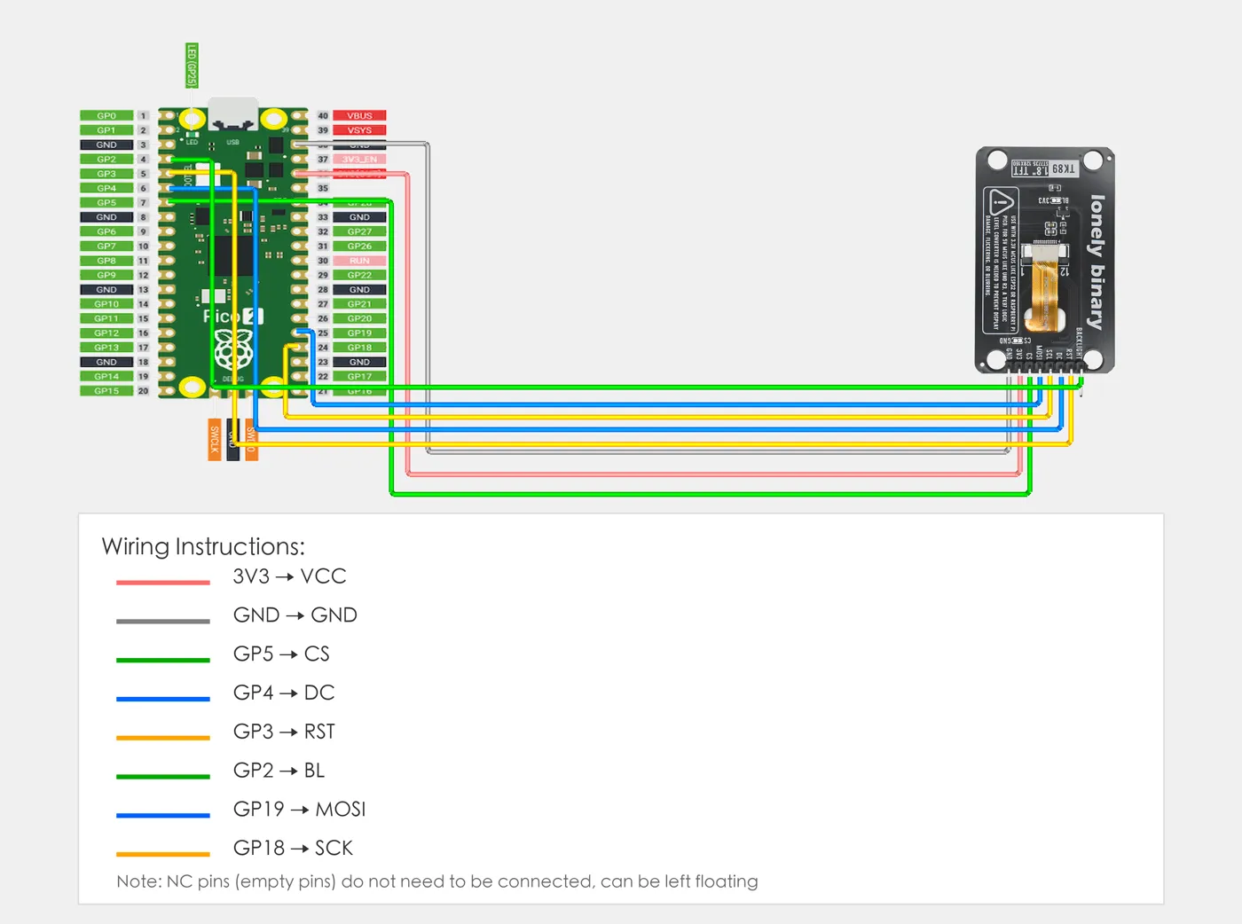
Eight wires, Adafruit's ST7735 library, and a sketch that sets BL HIGH before anything else, then fills the screen red, green, blue, white and black with each colour's name printed on it. If a name lands on the wrong colour, the colour order or inversion needs changing, and the sketch has the lines for both.
Eight wires
| Pin | ESP32-S3 | ESP32 | Pico | Uno, through a TK97 |
|---|---|---|---|---|
| BL | GPIO 41 | GPIO 32 | GP2 | D7 |
| RST | GPIO 42 | GPIO 4 | GP3 | D8 |
| DC | GPIO 2 | GPIO 2 | GP4 | D9 |
| SCL | GPIO 12 | GPIO 18 | GP18 | D13 |
| MO | GPIO 11 | GPIO 23 | GP19 | D11 |
| CS | GPIO 10 | GPIO 15 | GP5 | D10 |
| 3V3 | 3V3 | 3V3 | 3V3(OUT) | the TK97's 3.3 V side |
| GND | GND | GND | GND | GND |
SCL and MO go to each board's hardware SPI clock and data out; the library finds them for itself. CS, DC, RST and BL can be any output pins, and the sketch names them at the top. On an Uno every line goes through the TK97, as three volts only explains.
One library
Install Adafruit ST7735 and ST7789 Library from Tools > Manage Libraries, and say yes to its dependencies, Adafruit GFX and Adafruit BusIO. GFX is where the drawing comes from: text, lines, rectangles, the same calls as on an OLED.
Lonely Binary's own display library covers the six-panel SPI TFT kit and ESP32 boards only, not this board, so this book does not use it.
Backlight first
setup() sets BL HIGH before it does anything else. The board holds the
backlight off until then, so if the sketch has a problem later, you can
still tell a dark screen from a white one.
Then initR(INITR_BLACKTAB) sends the controller its setup, and
setRotation(1) turns the picture landscape, 160 across and 128 down, the
way the board lies with its header on the left. Rotation 0 and 2 are
portrait, for the board stood with its header at the bottom.
What you should see
Red, green, blue, white and black, a second and a half each, each with its name printed in its top-left corner. Then the size, 160 x 128, and a yellow frame along the very edge. The serial monitor at 115200 says which colour should be showing.
If a name is on the wrong colour, the panel needs a different setting, not
different wiring. The owner's video of an older sketch shows this panel
drawing black as white with INITR_BLACKTAB, so expect to take the // off
tft.invertDisplay(true). If red shows blue, try INITR_REDTAB. When the
screen is wrong
has the whole table.
Here it is on the owner's own boards, running the older test sketch:
The code
Adafruit's ST7735 library over the board's hardware SPI. setup() sets BL HIGH first, then initR(INITR_BLACKTAB) and landscape rotation. loop() fills the screen with five colours, printing each colour's name on it, then draws a yellow frame round the edge and the screen's size.
/*
  1.8-inch TFT Display - first light                    TK89 / /p/tk89

  Wiring. The eight pins top to bottom, screen facing you, header on
  the left (the front prints BL RST DC SCL MO CS 3V3 GND):

    BL   -> GPIO 41 on an ESP32-S3, GPIO 32 on an ESP32, GP2 on a
            Pico, D7 on an Uno. The backlight is off until BL is
            HIGH.
    RST  -> GPIO 42 on an ESP32-S3, GPIO 4 on an ESP32, GP3 on a
            Pico, D8 on an Uno
    DC   -> GPIO 2 on an ESP32-S3, GPIO 2 on an ESP32, GP4 on a
            Pico, D9 on an Uno
    SCL  -> the SPI clock: GPIO 12 on an ESP32-S3, GPIO 18 on an
            ESP32, GP18 on a Pico, D13 on an Uno
    MO   -> MOSI, SPI data out: GPIO 11 on an ESP32-S3, GPIO 23 on
            an ESP32, GP19 on a Pico, D11 on an Uno
    CS   -> GPIO 10 on an ESP32-S3, GPIO 15 on an ESP32, GP5 on a
            Pico, D10 on an Uno
    3V3  -> 3V3. Never 5V: the display is a 3.3 V part.
    GND  -> GND

  An Uno is a 5 V board: every line goes through a TK97 logic
  level converter, never straight to these pins.

  Arduino IDE
    Tools > Board                 your board, e.g. ESP32S3 Dev Module
    Tools > Port                  the one that appears when you plug in
    Tools > USB CDC On Boot       Enabled   (ESP32-S3 only)
    Tools > Manage Libraries      Adafruit ST7735 and ST7789 Library,
                                  and install its dependencies
                                  (Adafruit GFX, Adafruit BusIO)
*/

#include <Adafruit_GFX.h>
#include <Adafruit_ST7735.h>
#include <SPI.h>

// CS, DC, RST and BL are any output pins. SCL and MO are the
// board's own SPI pins, which SPI picks for itself.
#if defined(ARDUINO_ARCH_AVR)              // Uno, through a TK97
const int TFT_CS = 10, TFT_DC = 9, TFT_RST = 8, TFT_BL = 7;
#elif defined(CONFIG_IDF_TARGET_ESP32S3)   // ESP32-S3
const int TFT_CS = 10, TFT_DC = 2, TFT_RST = 42, TFT_BL = 41;
#elif defined(ARDUINO_ARCH_ESP32)          // ESP32
const int TFT_CS = 15, TFT_DC = 2, TFT_RST = 4, TFT_BL = 32;
#else                                      // Raspberry Pi Pico
const int TFT_CS = 5, TFT_DC = 4, TFT_RST = 3, TFT_BL = 2;
#endif

Adafruit_ST7735 tft(TFT_CS, TFT_DC, TFT_RST);

// Fill the screen and print the colour's name on it, so a
// swapped colour shows as a name on the wrong colour.
void panel(uint16_t colour, const char *name, uint16_t ink) {
  tft.fillScreen(colour);
  tft.setTextColor(ink);
  tft.setTextSize(2);
  tft.setCursor(8, 8);
  tft.print(name);
  Serial.print("now showing: ");
  Serial.println(name);
  delay(1500);
}

void setup() {
  Serial.begin(115200);
  delay(500);

  // The backlight first. Q2 on the board keeps it off until BL
  // is HIGH, so a dark screen here is BL, not the picture.
  pinMode(TFT_BL, OUTPUT);
  digitalWrite(TFT_BL, HIGH);

  // The panel's type. If the colours come out wrong or there is
  // a band of noise at one edge, try INITR_GREENTAB or
  // INITR_REDTAB here. The handbook's last chapter has the table.
  tft.initR(INITR_BLACKTAB);
  // If BLACK shows as white, the panel wants its colours inverted.
  // The owner's video of an older sketch suggests this one does:
  // take the // off the next line if so.
  // tft.invertDisplay(true);

  tft.setRotation(1);   // 1 or 3: landscape. 0 or 2: portrait.
  Serial.println("TK89 first light: 160 x 128, landscape");
}

void loop() {
  panel(ST77XX_RED, "RED", ST77XX_WHITE);
  panel(ST77XX_GREEN, "GREEN", ST77XX_BLACK);
  panel(ST77XX_BLUE, "BLUE", ST77XX_WHITE);
  panel(ST77XX_WHITE, "WHITE", ST77XX_BLACK);
  panel(ST77XX_BLACK, "BLACK", ST77XX_WHITE);

  tft.setTextSize(1);
  tft.setCursor(8, 40);
  tft.print(tft.width());
  tft.print(" x ");
  tft.print(tft.height());
  tft.print(" pixels");
  tft.drawRect(0, 0, tft.width(), tft.height(), ST77XX_YELLOW);
  delay(3000);
}
The pins at the top follow the table: the #if picks them for an Uno, an ESP32-S3, an ESP32 or a Pico. SCL and MO are not in the sketch: SPI uses the board's own. The sketch compiles for an Uno, an ESP32 and an ESP32-S3.
View on GitHub · blocks/tk89-tft-1-8-inch/arduino/tft_first_light/tft_first_light.ino @ v1.6The same test in MicroPython, for an ESP32, an ESP32-S3 or a Pico, on boochow's ST7735.py driver, which you copy to the board first. It picks the pins by board, sets BL HIGH, and prints each colour's name with MicroPython's own framebuf font.
"""
  1.8-inch TFT Display - first light, MicroPython       TK89 / /p/tk89

  Wiring. The eight pins top to bottom, screen facing you, header on
  the left (the front prints BL RST DC SCL MO CS 3V3 GND):

    BL   -> GPIO 41 on an ESP32-S3, GPIO 32 on an ESP32, GP2 on a
            Pico. The backlight is off until BL is HIGH.
    RST  -> GPIO 42 on an ESP32-S3, GPIO 4 on an ESP32, GP3 on a Pico
    DC   -> GPIO 2 on an ESP32-S3, GPIO 2 on an ESP32, GP4 on a Pico
    SCL  -> GPIO 12 on an ESP32-S3, GPIO 18 on an ESP32, GP18 on a
            Pico (the SPI clock)
    MO   -> GPIO 11 on an ESP32-S3, GPIO 23 on an ESP32, GP19 on a
            Pico (MOSI, SPI data out)
    CS   -> GPIO 10 on an ESP32-S3, GPIO 15 on an ESP32, GP5 on a Pico
    3V3  -> 3V3   (never 5V: the display is a 3.3 V part)
    GND  -> GND

  Thonny
    Run > Configure interpreter   MicroPython (ESP32) or
                                  MicroPython (Raspberry Pi Pico)
    The driver is one file: ST7735.py from boochow's
    MicroPython-ST7735 on GitHub. Open it in Thonny and save it
    to the board under that name, then run this.
"""

import os
import sys
import time
import framebuf
from machine import SPI, Pin
from ST7735 import TFT

# The pins, by board. SCL and MO go to the SPI unit's clock and
# data out; the other four are any output pins.
if sys.platform == "rp2":                   # Raspberry Pi Pico
    SCL, MOSI, CS, DC, RST, BL = 18, 19, 5, 4, 3, 2
    SPI_ID = 0
elif "ESP32S3" in os.uname().machine:       # ESP32-S3
    SCL, MOSI, CS, DC, RST, BL = 12, 11, 10, 2, 42, 41
    SPI_ID = 1
else:                                       # ESP32
    SCL, MOSI, CS, DC, RST, BL = 18, 23, 15, 2, 4, 32
    SPI_ID = 2

# The backlight first: Q2 on the board keeps it off until BL is
# HIGH, so a dark screen here is BL, not the picture.
backlight = Pin(BL, Pin.OUT, value=1)

# 10 MHz: under the controller's rated 15 MHz for writes.
spi = SPI(SPI_ID, baudrate=10_000_000, polarity=0, phase=0,
          sck=Pin(SCL), mosi=Pin(MOSI))
tft = TFT(spi, DC, RST, CS)

# The panel's type. If the colours come out wrong or there is a
# band of noise at one edge, try tft.initg() or tft.initb().
tft.initr()
tft.rgb(True)            # False if red and blue come out swapped
# tft.invertcolor(True)  # if BLACK shows as white
tft.rotation(1)          # 1 or 3: landscape. 0 or 2: portrait.
W, H = tft.size()


def swap(colour):
    # framebuf stores a pixel low byte first; the display wants
    # the high byte first.
    return ((colour & 0xFF) << 8) | (colour >> 8)


def label(x, y, text, ink, paper):
    # Draw text into a small buffer, then send just that
    # rectangle: MicroPython's framebuf has an 8 x 8 font.
    w, h = 8 * len(text), 8
    buf = bytearray(w * h * 2)
    fb = framebuf.FrameBuffer(buf, w, h, framebuf.RGB565)
    fb.fill(swap(paper))
    fb.text(text, 0, 0, swap(ink))
    tft.image(x, y, x + w - 1, y + h - 1, buf)


PANELS = [
    (TFT.RED, "RED", TFT.WHITE),
    (TFT.GREEN, "GREEN", TFT.BLACK),
    (TFT.BLUE, "BLUE", TFT.WHITE),
    (TFT.WHITE, "WHITE", TFT.BLACK),
    (TFT.BLACK, "BLACK", TFT.WHITE),
]

print("TK89 first light:", W, "x", H)
while True:
    for colour, name, ink in PANELS:
        tft.fill(colour)
        label(8, 8, name, ink, colour)
        print("now showing:", name)
        time.sleep(1.5)
    label(8, 24, "%d x %d pixels" % (W, H), TFT.WHITE, TFT.BLACK)
    tft.rect((0, 0), (W, H), TFT.YELLOW)
    time.sleep(3)
There is no Uno here: an Uno cannot run MicroPython. The driver's initr(), initg() and initb() are its panel types; rgb(False) swaps red and blue, invertcolor(True) inverts. Stop it with Ctrl-C.
View on GitHub · blocks/tk89-tft-1-8-inch/micropython/tft_first_light.py @ v1.6When it does not work
The backlight works and the controller never took its setup. Check RST, DC, SCL and MO against the table, and that the pin numbers at the top of the sketch match your wiring. SCL goes to your board's SPI clock, MO to its SPI data out.
The backlight is off: BL is not on the pin the sketch drives, or not wired. With BL unwired the board keeps the backlight off. Check BL, then 3V3 and GND.
The panel wants its colours inverted. Take the // off tft.invertDisplay(true) in setup() and upload again. In the owner's video of an older sketch this panel did show black as white, so expect to need it.
Set Tools > USB CDC On Boot to Enabled and upload again. Without it the S3's USB port does not bring up a serial port at boot, and the sketch runs with nowhere to print.
Install the library: Tools > Manage Libraries, search for Adafruit ST7735, install Adafruit ST7735 and ST7789 Library, and accept its dependencies, Adafruit GFX and Adafruit BusIO.
What the four signal wires are doing while that red goes in.
Clock, data, DC and CS →Edit this page — content/books/tft-1-8-inch/first-light.mdx
Questions about this product
See what other owners have asked, and read their solutions.
1.8-inch TFT Display
Loading discussions…
Discuss this article
Ask about this page. The answer stays here, on the page it belongs to, for whoever hits the same wall next.