What is on the board
The TK39 is a 22.4 × 38.4 mm board with a DHT22 lying flat across it, grille up, a 10 kΩ pull-up hidden under the cage, and a four-pin header of which three pins are wired. It is the TK38's circuit with the better sensor on it, which is why the wiring is the same and the board is 8 mm longer.
Front and back
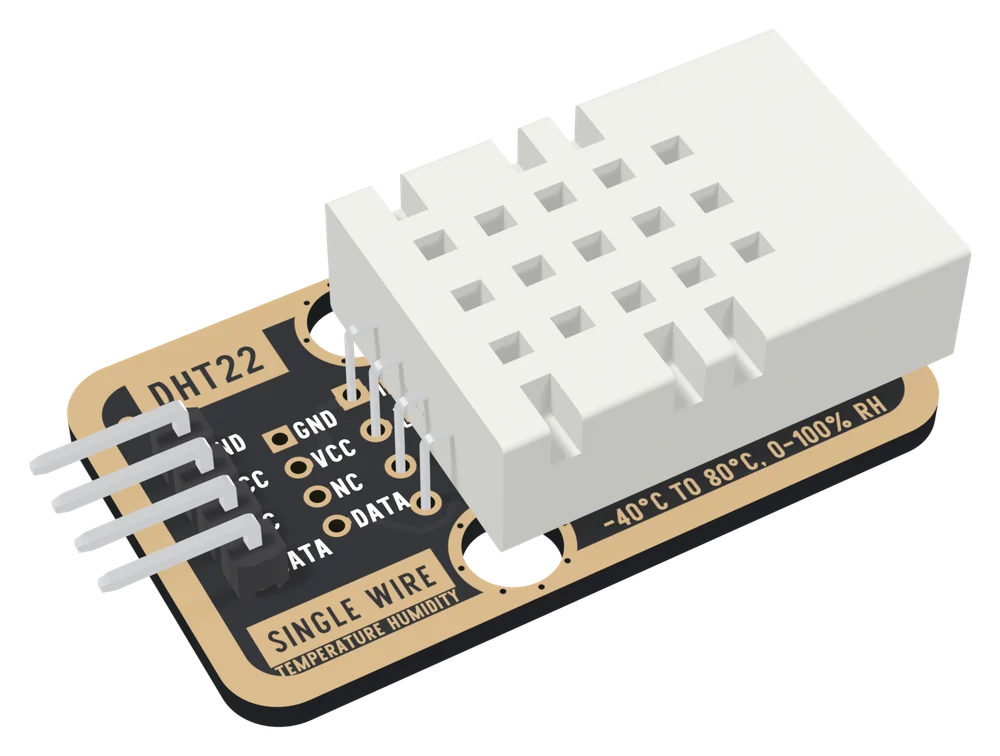
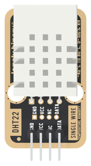
The front says what it is and how far it goes: DHT22, SINGLE WIRE, TEMPERATURE HUMIDITY and -40°C TO 80°C, 0-100% RH, the same range as the datasheet's §3. The four pins are printed twice, at the header and at the open holes above it.
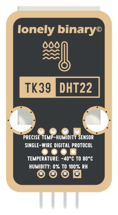
The back carries the part number, TK39 DHT22, and no pin names. Turned over, the square GND pad is on the right, which is the one mirror to watch for if you ever solder wires to the back.
Part by part
Pick a part and the drawing rings it. Every position is from the board's pick-and-place file and drill file, and the outline is the Gerber's.
There are four things on the board and one of them measures anything. The DHT22 (HAIGU, LCSC C2880291) lies flat with its legs bent 90° into the board. R1 is a 10 kΩ 0805 resistor from VCC to DATA, the pull-up every DHT needs, so you add nothing. H1 is the header you wire. U14 is a footprint for a 2.0 mm connector, on the bill of materials and open on every board in the kit photograph.
The two round holes are 4.8 mm across and 16 mm apart, the width of a LEGO stud and two studs apart, like every TinkerBlock's. They connect to nothing. The cage covers the upper part of both, so a stud fits but a screw head there hits the sensor.
This book quotes Aosong's DHT22 datasheet, the part the name comes from. The sensor fitted, per the bill of materials, is HAIGU's DHT22.
The same circuit as the TK38
The net list has three nets and they are the TK38's: GND, VCC, and DATA with R1 on it. NC on the header reaches nothing, and neither does the DHT22's own third leg, which its datasheet §4 calls NULL. The four pins in the DHT11 book walks through them; everything there applies to this board.
What differs is size. The PCB is 22.4 × 38.4 mm, 8 mm longer than the TK38's, because the DHT22 is the bigger part: about 17.5 × 25.1 mm and 7.7 mm thick, lying 0.7 mm over the board with its end about 1 mm past the top edge. The header pins add 3.5 mm at the bottom.
The pull-up is why VCC matters: DATA idles at whatever you feed VCC. 3.3 V or 5 V is that argument in full, and the next article wires it.
When it does not work
Hold the board sensor side up with the header at the bottom. The square pad is on the left and is GND, then VCC, NC and DATA. The sensor's own legs are in a different order, VCC, DATA, NC, GND. The board's tracks put them right, so wire to the header's labels.
Those are an unfitted 2.0 mm connector footprint on the same GND, VCC and DATA as the header, with its own NC. The board ships with nothing in them. Leave them alone unless you want to solder a 2.0 mm connector there.
R1, the 10 kΩ pull-up from VCC to DATA, sits under the lead end of the sensor's cage, where the pick-and-place file puts it. You cannot see it without lifting the sensor, and you do not need to: it is fitted on every TK39.
You can desolder it, but the board is the convenient part: the pull-up, the pin order and the header are done. A bare DHT22 needs its own pull-up between VCC and DATA, and its legs are VCC, DATA, NC, GND.
Edit this page — content/books/dht22/whats-on-the-board.mdx
Questions about this product
See what other owners have asked, and read their solutions.
This page covers several products. Choose yours to see the right discussions.
Discuss this article
Ask about this page. The answer stays here, on the page it belongs to, for whoever hits the same wall next.