What is on it
Four parts and a header. A reed switch in a 14 mm glass tube, a 10 kΩ that holds SIGNAL LOW while it is open, and a red LED with its 1 kΩ that lights whenever it is closed. Nothing on the board runs on its own: open, it draws no current at all.
The glass across the top
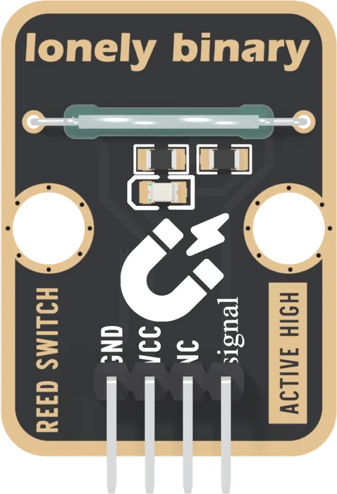
The glass tube is the sensor. It is an MKA-14103 reed switch: two thin blades sealed inside glass 2.3 mm across and 14 mm long, their tips overlapping in the middle with a small gap between them. It is normally open, and a magnet closes it. The part is ordered sorted to 15 to 18 ampere-turns, a measure of how strong a field closes it that two blades in glass explains.
Pick each part. Under the tube are three 0805 parts:
- R9, 10 kΩ, from SIGNAL to GND: the pull-down. It gives SIGNAL a definite LOW while the switch is open.
- R8, 1 kΩ, and the LED, also from SIGNAL to GND. When the switch closes, SIGNAL is at VCC and the LED lights, about 1.3 mA from 3.3 V and 3 mA from 5 V (a red LED's usual 2 V drop, worked out, not measured).
Nothing draws current while it waits
VCC reaches one lead of the switch and nothing else. With no magnet there is no path from VCC anywhere, so the block takes no current at all. Closed, it takes what the pull-down and the LED need: about 1.6 mA at 3.3 V. For a battery project, that makes the resting state matter, which the pull-down and the light works through.
When it does not work
Yes. The LED hangs off SIGNAL and is fed from VCC through the closed switch, so it lights whenever a magnet closes it and the block has VCC and GND, whatever your board is doing. It is a switch light, not a power light.
Do not. The leads go into glass, and bending them near the tube is how the seal cracks. Move the magnet, or turn the whole block, instead.
Yes, it is thin glass 2.3 mm across. Keep screws, clips and fingers off it, and do not press the magnet against it hard. A cracked tube can still look fine and stop switching.
Edit this page — content/books/reed-switch/what-is-on-it.mdx
Questions about this product
See what other owners have asked, and read their solutions.
Reed Switch
Loading discussions…
Discuss this article
Ask about this page. The answer stays here, on the page it belongs to, for whoever hits the same wall next.