What is on it
Six parts. A 12 mm gold pad that is the whole sensor, a TTP223 touch chip beside it, a 22 pF capacitor that sets how keen the pad is, a 100 nF one that steadies the chip's supply, and a red LED with its 1 kΩ resistor on the output. Nothing moves and nothing needs setting.
The parts
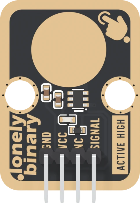
Pick a part to ring it. There are six, and two of them do the sensing: the pad and the chip.
The pad is a 12 mm disc of copper, plated gold like the edge, joined by one short track to the chip's sense input. It is not a button and there is nothing under it. Tontek asks for that track to be as short as possible and kept away from other tracks, because every millimetre of it is part of what the chip measures.
The chip is a Tontek TTP223, a one-key touch detector in a six-pin SOT-23 package. It runs on 2.0 to 5.5 V and draws about 1.5 µA while idle, so it costs nothing worth counting on a battery. Of its six pins, two are supply, one is the pad, one is the output, and two choose how the output behaves.
The mode is set in copper
Those two option pins are TOG and AHLB. TOG picks momentary or toggle; AHLB picks active-high or active-low. The datasheet's table:
| TOG | AHLB | Output |
|---|---|---|
| 0 | 0 | momentary, active high |
| 0 | 1 | momentary, active low |
| 1 | 0 | toggle, starts LOW |
| 1 | 1 | toggle, starts HIGH |
On this board both are soldered to GND, the first row, and that is the only behaviour it has. There is no jumper pad to cut or bridge.
The two capacitors and the light
C5, 22 pF, runs from the pad to GND. Tontek calls it Cs, and it is the sensitivity control: the chip looks for a change in the total capacitance on its input, so the more fixed capacitance sits there, the smaller a share a finger adds. None is the keenest; the datasheet allows up to 50 pF.
C4, 100 nF, sits across the chip's supply pins. The datasheet makes it compulsory: a supply that jumps looks like a touch.
LED2 and R1 run from SIGNAL to GND, a red LED and 1 kΩ. The LED lights whenever SIGNAL is HIGH, with no microcontroller involved, which makes it the first thing to look at when something does not work.
When it does not work
There is none on this board. The chip's two option pins, TOG and AHLB, are soldered to GND in the copper, which selects momentary, active-high output and nothing else. Tutorials that bridge a pad on the back are describing a different TTP223 board. Toggle is a few lines in the sketch.
No. It sits on SIGNAL, so it lights only while the pad is touched. A powered, untouched block shows no light at all, which is easy to mistake for a dead one. Touch the pad to check.
The part that sets it is C5, the 22 pF capacitor beside the pad. A smaller value makes the pad keener, a larger one duller, within the 0 to 50 pF the datasheet allows. It is an 0603 part, so changing it takes a fine soldering iron.
What the chip measures, and why a panel in front of the pad changes it.
A finger is a capacitor →Edit this page — content/books/tp223-touch-sensor/what-is-on-it.mdx
Questions about this product
See what other owners have asked, and read their solutions.
This page covers several products. Choose yours to see the right discussions.
Discuss this article
Ask about this page. The answer stays here, on the page it belongs to, for whoever hits the same wall next.