What is on it
Six parts and a header. A 5 mm infrared LED standing on the board, an S8050 transistor that switches it, 150 Ω that sets its current from VCC, 1 kΩ between SIGNAL and the transistor, and a red LED on the same transistor that shows when the infrared one is on. Off, it draws nothing.
The LED that stands up
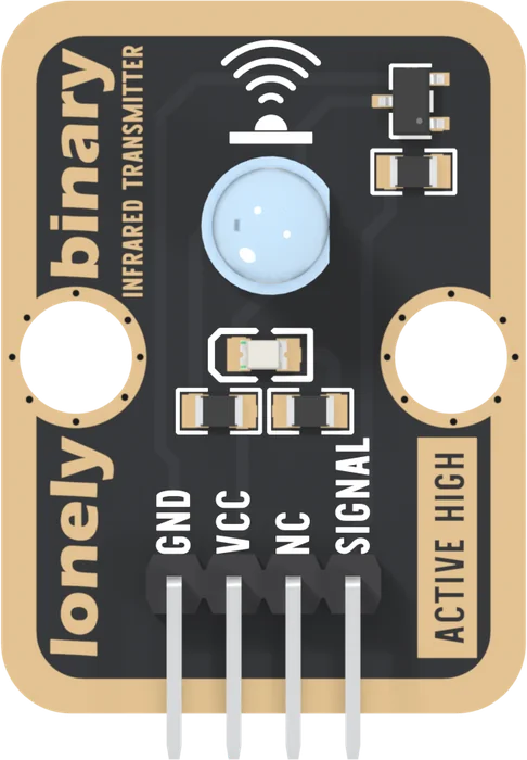
The round lens is an Everlight IR333C-A, a 5 mm infrared LED. Its light peaks at 940 nm, past the red end of what an eye can see, so it looks the same lit or dark. It stands on its two legs and points straight up, away from the parts side.
Pick each part. Around the LED are five small ones:
- Q1, an S8050, the three-legged part at the top right: an NPN transistor. Its emitter is GND and both LEDs end at its collector, so it switches them both.
- R9, 1 kΩ, beside it: the only thing SIGNAL is connected to. It leads into the transistor's base.
- R11, 150 Ω, bottom left: from VCC to the infrared LED, and the only thing that sets its current. About 13 mA from 3.3 V and 24 mA from 5 V, worked out from the data sheet, not measured.
- The red LED and R10, 1 kΩ: on the same transistor as the infrared LED, so it lights exactly when the infrared one does.
A light you can see for one you cannot
The red LED is there because the infrared one gives no sign of working. Both hang between VCC and the transistor, so the red one lights whenever the infrared one is on, and it is your first check, before a camera or a receiver.
Off, nothing flows: VCC reaches only the two resistors, and the transistor blocks both. On, the block takes about 27 mA from a 5 V rail, almost all of it for the infrared LED.
When it does not work
The 5 mm one standing up near the top of the board. The small flat LED lower down, between the mounting holes, is the red indicator. The infrared LED looks exactly the same lit or dark.
Gently, by its legs, well above the board, and only once or twice: the legs are the only thing holding it. It is easier to stand the whole block on its edge with its LED facing the receiver.
It lights whenever SIGNAL is HIGH, and nothing on the board holds SIGNAL LOW. A pin that floats or is pulled up before your sketch starts can switch the transistor on. Once setup() drives the pin LOW, both LEDs go dark.
Edit this page — content/books/ir-transmitter/what-is-on-it.mdx
Questions about this product
See what other owners have asked, and read their solutions.
Infrared Transmitter
Loading discussions…
Discuss this article
Ask about this page. The answer stays here, on the page it belongs to, for whoever hits the same wall next.