The four pins
Four pins, three of them wired: GND on the square pad, VCC to the Hall chip and its capacitor, and SIGNAL, the chip's output, which is a voltage for analogRead rather than a HIGH or a LOW. NC is connected to nothing. There is no resistor and no LED on the board.
Three wires and a spare
The header is four right-angle pins, 2.54 mm apart, printed GND, VCC, NC and SIGNAL from left to right with the parts facing you. GND is on the square pad, and that pad is the only way to tell four identical holes apart. Count from it.
Pick a pin to see where it goes. GND is the chip's ground and the bottom of both capacitors. VCC powers the chip. SIGNAL is the chip's output with a 100 nF capacitor to GND. NC is in no net at all.
A voltage, not a level
The front prints ANALOG in a box, and it means it. SIGNAL is not HIGH or
LOW. With no magnet near it sits at half of VCC, and a magnet moves it up
or down from there by a few millivolts per gauss. Read it with
analogRead, on an analog pin.
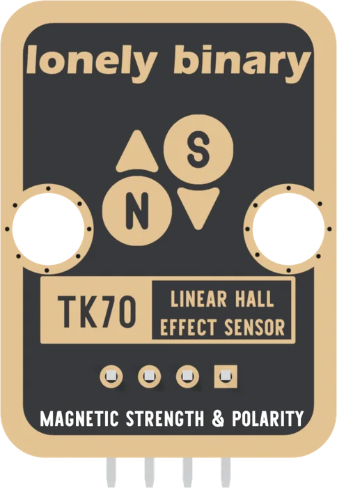
That is the difference from the TK18 Hall switch, which gives one bit: a field past its threshold or not, from either pole. The TK70 gives the field's strength and which way it points, which is what MAGNETIC STRENGTH & POLARITY on the back says.
VCC is not a free choice
The output swings up to about 0.8 of VCC with a strong field, so VCC decides the highest voltage your pin sees. Wire it to the voltage your board's pins run at: 3V3 on an ESP32, an ESP32-S3 or a Pico, 5V on an Uno. VCC sets the zero and the scale shows what the wrong one does.
When it does not work
The square pad. From the front, parts up and pins pointing down, it is the left-hand pin, and the order is GND, VCC, NC, SIGNAL. The back prints no pin names; turned over, the square pad is on the right and it is still GND.
No. It is soldered to a pad that no trace reaches, so it makes no difference either way. It is there so every TinkerBlock block has the same four-pin header and one cable fits all of them.
Not usefully. SIGNAL rests at half of VCC with no field, which is neither a clean HIGH nor a clean LOW, and the whole point of this block is the number in between. Use analogRead on an analog pin. For a plain yes or no, the TK18 Hall switch is the block for it.
There is nothing to light: the board has no LED. Read SIGNAL instead. With VCC and GND wired and no magnet near, it sits at about half of VCC, about 512 on an Uno.
Edit this page — content/books/linear-hall-sensor/the-four-pins.mdx
Questions about this product
See what other owners have asked, and read their solutions.
Linear Hall Effect Sensor
Loading discussions…
Discuss this article
Ask about this page. The answer stays here, on the page it belongs to, for whoever hits the same wall next.