What is on the board
Five XL-5050RGBC-WS2812B LEDs in a column, a four-pin right-angle header printed GND, VCC, NC and DATA, and two LEGO holes down the left side. Nothing else: no capacitor, no resistor, and no pin that carries the data past the fifth LED.
One block, assembled
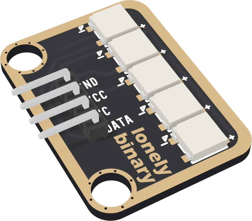
The bar arrives with the right-angle header soldered on. It is the standard TinkerBlock size, 22.4 × 30.4 mm, but its two LEGO holes are both on the left, 24 mm apart, one above the header and one below it.
Five LEDs and four pins
The five squares are XINGLIGHT XL-5050RGBC-WS2812B LEDs, 5 × 5 mm, one every 5.475 mm. Each is a red, a green and a blue LED with a driver chip that holds them at a constant 12 mA per colour at full brightness, in 256 steps.
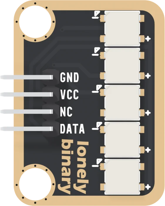
| Pin | Connected to | Wire it to |
|---|---|---|
| GND | Every LED's ground | Your board's GND |
| VCC | Every LED's supply | Your board's 5V, not 3V3 |
| NC | Nothing | Nothing |
| DATA | LED1's data input | One GPIO |
The header reads GND, VCC, NC, DATA from the top. DATA is the bottom pin and goes straight into the top LED, with nothing between them. From there each LED's output feeds the next one's input, down to LED5.
The back
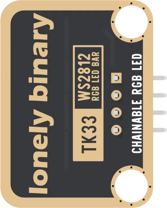
The line of text up the back's right edge says the bar can be extended with another. It cannot. LED5's output pin is soldered to a pad that no trace reaches, and no pin or hole on the board carries it anywhere.
What is not on it
A WS2812 design usually adds a 100 nF capacitor beside each LED and a resistor of a few hundred ohms in the data line. The data sheet asks for both, the resistor against spikes when a board is plugged in live. This bar has neither, so make the wires with the USB cable out.
When it does not work
The top one, nearest the top LEGO hole, with the header's pins pointing left. DATA goes straight into its input, and the chain runs downward, so the bottom LED is pixel 4. Turn the bar upside down on a project and the numbers run the other way; the sketch can simply count backwards.
No. It is soldered to a pad that no copper reaches, so a wire in it goes nowhere. It is there so every TinkerBlock header has four pins. The mistake it invites is a jumper in NC instead of DATA, one hole up, which leaves every LED dark.
Not on this board. The fifth LED's output is on a pad that no trace, pin or hole reaches, so there is nothing to connect a second bar to. The print on the back is wrong. To drive two bars, give the second its own GPIO.
The board was made without them. The LED's data sheet asks for a 100 nF capacitor across each LED's supply and a resistor in the data line. On a short jumper from a USB-powered board the bar runs without them; the practical rule is to connect it with the power off and keep the brightness sensible.
Edit this page — content/books/ws2812-led-bar/whats-on-the-board.mdx
Questions about this product
See what other owners have asked, and read their solutions.
WS2812 RGB LED Bar
Loading discussions…
Discuss this article
Ask about this page. The answer stays here, on the page it belongs to, for whoever hits the same wall next.