The four pins
Four pins, two of them wired: GND on the square pad and SIGNAL at the other end. Both middle pins are printed NC and are connected to nothing, because nothing on this block is powered. The disc makes its own voltage.
Two wires and two spares
The header is four right-angle pins, 2.54 mm apart, printed GND, NC, NC and SIGNAL. GND is on the square pad, and that pad is the only way to tell four identical holes apart. Count from it.
Pick a pin to see where it goes. GND is where everything on the board ends, the disc's black lead included. SIGNAL is the top of a 100 nF capacitor, fed from the disc through 1 kΩ. The two NC pins are in no net at all.
On most TinkerBlock blocks the pin after GND is VCC. On this one it is not. The disc turns a bend into a charge of its own, and the four parts on the board are a resistor, a diode, another resistor and a capacitor: none of them needs power. So there is nothing to feed, and two wires are the whole connection.
The pads that say VCC
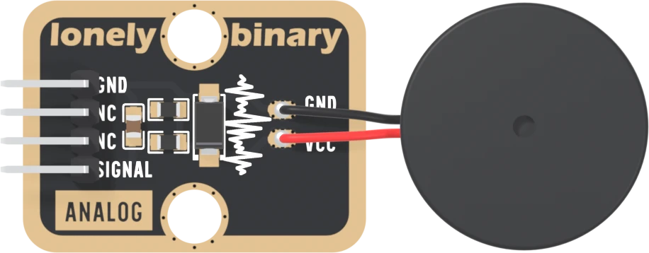
Near the right-hand edge, the disc's two leads are soldered to two small pads. The black lead is on the pad printed GND. The red lead is on the pad printed VCC, and that label is the one thing on the board that misleads: the pad is the disc's own node, the point where the diode, the 1 MΩ and the 1 kΩ meet. It is not a supply and nothing outside the block goes to it.
The same two pads are repeated on the back, so the disc could be soldered on either face.
What SIGNAL does
SIGNAL sits at 0 V while nothing touches the disc. A tap lifts it within
about a millisecond, and it drains back to 0 V over a tenth of a second or
so. How high it goes says roughly how hard the tap was, so it is read with
analogRead, not digitalRead. The first
reading wires it up.
When it does not work
Nowhere. The header prints GND, NC, NC, SIGNAL, and the two NC pins are in no net on the board: there is no VCC pin. The disc makes its own charge when it bends, and the four parts on the board need no supply. Older pages for this block said to wire VCC to 3.3 V or 5 V; that was wrong, and harmless only because the pin goes nowhere.
No. The disc's red lead is soldered to a pad printed VCC, but that pad is the disc's own node, where the diode, the 1 MΩ and the 1 kΩ meet. Nothing on your side connects to it, and nothing should: the disc is soldered on.
The square pad. With the block turned as the pictures show it, header on the left and the disc on the right, GND is the top pin and SIGNAL the bottom one. With the header at the bottom, GND is on the left. The back prints no pin names.
Edit this page — content/books/piezo-sensor/the-four-pins.mdx
Questions about this product
See what other owners have asked, and read their solutions.
Piezo-Ceramic Sensor
Loading discussions…
Discuss this article
Ask about this page. The answer stays here, on the page it belongs to, for whoever hits the same wall next.