What is on the board
Five parts, and three of them are hidden under the matrix: the MAX7219 that drives it, R7, the resistor that sets how hard every LED is driven, and a 100 nF capacitor. The board is 32 by 41 mm, bigger than a small TinkerBlock, because the matrix alone is 32 mm across.
Three parts under the matrix
The matrix is a 1088AS: sixty-four LEDs in a 32 mm square, eight rows and eight columns sharing sixteen legs between them. No LED has a wire of its own.
The MAX7219 is the chip that makes that work. It holds the picture in eight registers, one byte each, and lights them one column at a time over and over. On this board it is HGSEMI's MAX7219M, a second maker's copy with the same pins, registers and datasheet numbers.
R7 is the one resistor the chip needs. It runs from VCC to the chip's ISET pin, and the chip copies about a hundred times the current through it into every LED that is lit. At 10 kΩ that is about 40 mA, the top of the chip's range. Brightness is then set by time, not by this resistor: Brightness is time, not current.
C2, 100 nF across the supply, steadies VCC while the chip switches whole columns on and off.
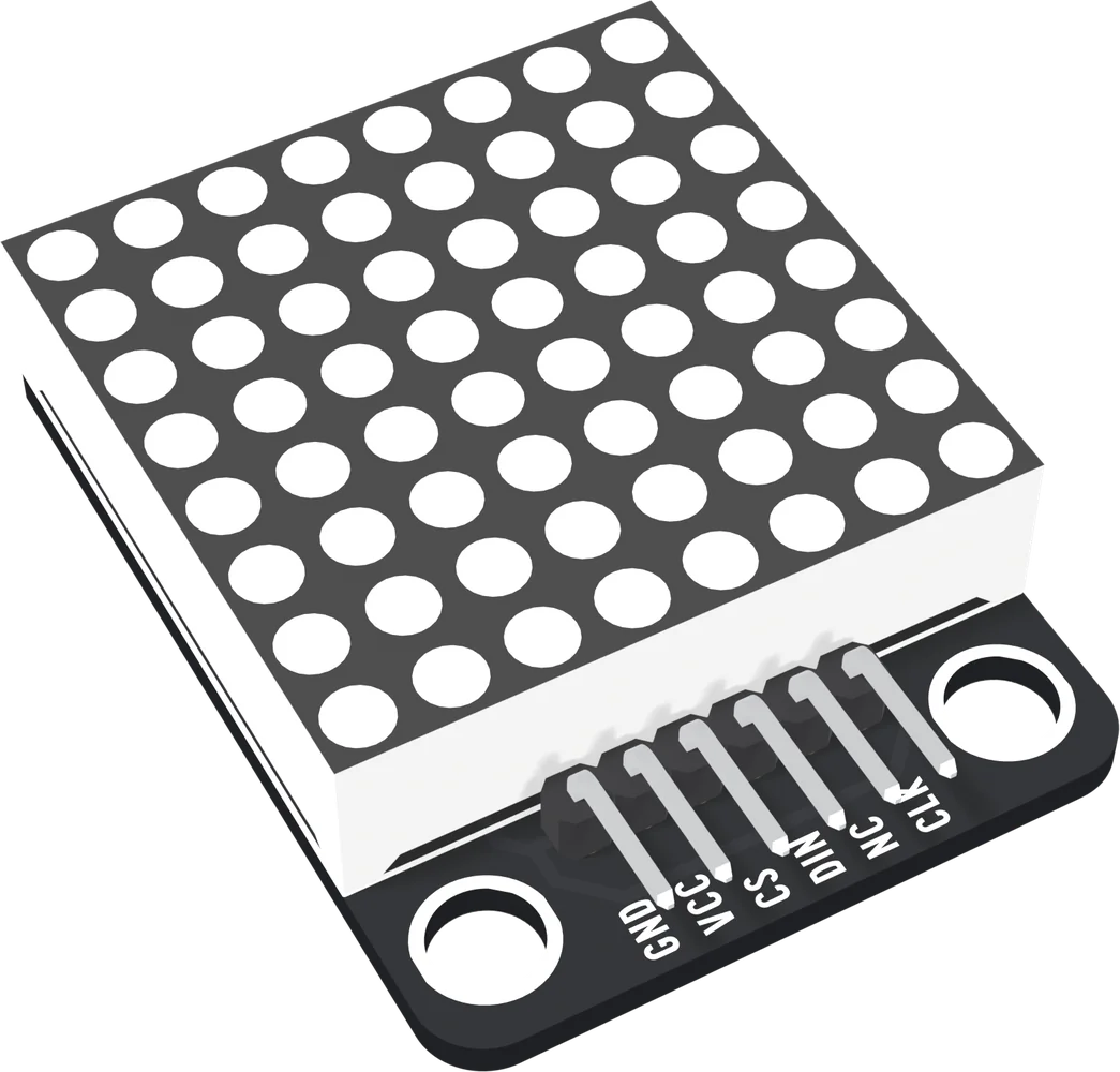
Not a small block
The board is 32 × 41 mm. The matrix sets the width; the header strip and the two mounting holes, 24 mm apart, take the last 9 mm. The top two corners are square and the matrix runs right to them.
When it does not work
Not without taking the matrix off. The MAX7219, R7 and C2 are all soldered to the front of the board underneath the matrix package. The back shows only the matrix's sixteen legs and the header pads.
No. The only LEDs on the board are the sixty-four in the matrix, and the chip starts with them all off. A dark matrix after power-up is normal until a sketch wakes the chip.
It is 32 by 41 mm, not 22.4 by 30.4 mm. Its two mounting holes are 24 mm apart, below the header, so it takes a wider spot on the TinkerBlock baseplate than a small block does.
Not brighter: 10 kΩ already sets the LEDs near the 40 mA the chip is rated for, and the datasheet's minimum is 9.53 kΩ. Brightness is set in software, from the intensity register, without touching the board.
How sixty-four LEDs are driven from sixteen legs, and why it looks like all of them.
One column at a time →Edit this page — content/books/matrix-led/whats-on-the-board.mdx
Questions about this product
See what other owners have asked, and read their solutions.
This page covers several products. Choose yours to see the right discussions.
Discuss this article
Ask about this page. The answer stays here, on the page it belongs to, for whoever hits the same wall next.