The four pins
Four pins, left to right from the square pad: GND, VCC, NC and DATA. Three carry the board's three nets and the 10 kΩ pull-up is already across two of them. The third pin is connected to nothing, and it is the one that catches people counting from the wrong end.
Both faces
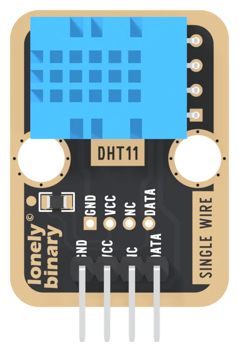
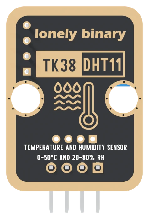
The front carries the pin names. The back carries the part number and the
range, which is how to identify a loose board: TK38 DHT11 over
0-50°C AND 20-80% RH. Turned over, the square pad is on the right, so count
from the square pad and not from an edge.
Pin by pin
The net list has three nets. GND joins header pin 1 to the sensor's GND leg. VCC joins pin 2 to the sensor's supply leg and one end of R1. DATA joins pin 4 to the sensor's data leg and the other end of R1.
GND is pin 1, on the square pad. The DHT11's own legs run VCC, DATA, NC, GND; the board puts ground first.
NC is connected to nothing. It is in no net. It exists because the sensor's third leg is unused, and it is the pin people skip when they wire by position. Be one pin out and DATA lands on a dead pad, which looks exactly like a dead sensor.
R1 is the pull-up, 10 kΩ from VCC to DATA, already fitted. It is what holds the data line high when nothing is pulling it low. Aosong's datasheet suggests 5 kΩ for cable up to 20 m; 10 kΩ is what DHT breakout boards generally fit, and it works on jumper wires. It matters only on a long cable, where a smaller resistor pulls the line up faster.
The second row of holes is a footprint for a 2.0 mm pitch connector, wired to the same three nets in the same order. It is a second place to attach a cable. Nothing is fitted there on the board in the pictures.
The board
| TK38 | |
|---|---|
| Size | 22.4 × 30.4 mm, pins standing 3.5 mm past the bottom edge |
| Header | 4 pins, 2.54 mm, right-angle |
| Pull-up | 10 kΩ, fitted |
| Mounting | two 4.8 mm holes, 16 mm apart |
The header is right-angle: the pins leave the board's bottom edge flat, so the block can lie on a table or a baseplate with the grille facing up.
When it does not work
GND, on the square pad. Every other pad on the header is round, so you can find it in a photograph as well as on the board. From there the order is GND, VCC, NC, DATA. On the back the order reads mirrored, so count from the square pad on either face.
Nothing. The net list has three nets, GND, VCC and DATA, and the third header pin is in none of them. The DHT11's own third leg is unused as well, which is why the pin exists. Wire nothing to it.
No. R1 is a 10 kΩ from VCC to DATA and it is already fitted. A bare DHT11 needs one added; the TK38 does not. A second one in parallel does no harm but gains nothing on ordinary jumper wires.
The footprint for a 2.0 mm pitch connector, on the same nets in the same order: GND, VCC, nothing, DATA. It is another place to attach a cable, not a way to chain a second sensor. Every DHT11 needs a data pin of its own.
Three wires, one library, and a sketch that prints a temperature.
The first reading →Edit this page — content/books/dht11/the-four-pins.mdx
Questions about this product
See what other owners have asked, and read their solutions.
DHT11 Temperature and Humidity Sensor
Loading discussions…
Discuss this article
Ask about this page. The answer stays here, on the page it belongs to, for whoever hits the same wall next.