
What is on it
Three parts and a header. A screw terminal that takes the sensor's two wires, a 5.1 kΩ resistor, and a red LED. Nothing on the board runs on its own, and nothing pulls SIGNAL anywhere: open, the board draws no current, and the LED is a signal light, not a power light.
The terminal across the top
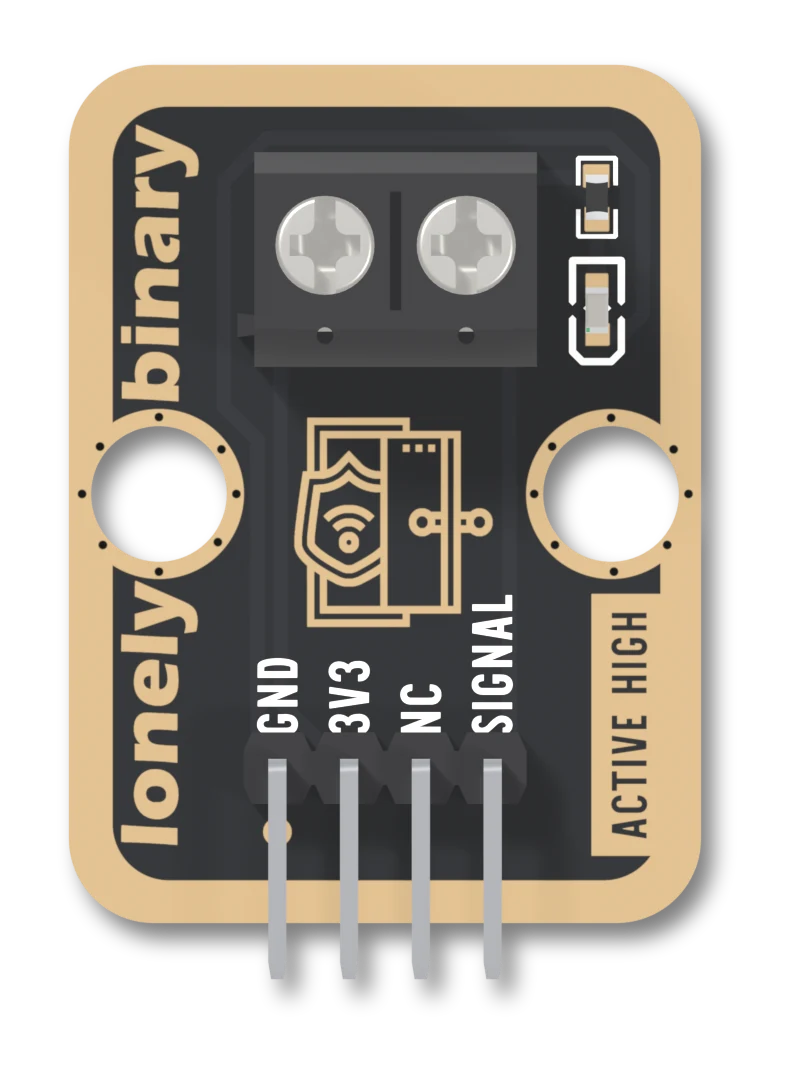
The black block is a two-way screw terminal with a 5.0 mm pitch. It is the whole reason for the board: it is where the sensor's two bare wires arrive. The screw on the right is SIGNAL and the one on the left is VCC, seen from the front with the header at the bottom. The sensor has no polarity, so the order does not matter.
The two small parts
- R1, 5.1 kΩ, and the red LED, in series, from SIGNAL to GND. They are the only thing on the board connected to SIGNAL besides the header and the terminal.
When SIGNAL is HIGH the LED lights, dimly, at about 0.25 mA from 3.3 V and 0.6 mA from 5 V (a red LED's usual 2 V drop, worked out, not measured). When SIGNAL is not HIGH it is dark.
What is not there
There is no resistor from SIGNAL to GND and none from SIGNAL to VCC. The LED's branch does not count: an LED does not conduct below about 1.8 V, so with the sensor open SIGNAL is connected to nothing. The board leaves the pull-down to you, and the next articles explain what that costs and how to add it.
The light is not a power light
The product listing says the LED shows that the module has power. It does not: it hangs off SIGNAL, not VCC. A powered board with the door open is dark, and a board with only the sensor and GND connected, no supply anywhere, would light up if the other side were driven. Use it as "the sensor is closed", which is what it says.
When it does not work
No. The LED is fed from SIGNAL, so it lights only while SIGNAL is HIGH: the sensor closed. With the door open the board can be fully wired and the LED still dark. It is not a power light, whatever the product listing says.
Probably. The 5.1 kΩ in series limits it to a fraction of a milliamp, about 0.25 mA at 3.3 V by arithmetic, so it is a faint light, not a bright one. It is there to show the state, not to light a room.
Either. A reed sensor is a switch with two bare wires and no polarity, so it does not matter which screw each one is under. Tighten the screw on the bare copper, not on the insulation.
Strip enough insulation that bare copper fills the terminal, push the wire all the way in and then tighten. A wire that is only caught by the insulation makes a contact that comes and goes, which looks exactly like a door opening and closing.
What the terminal joins, and what the board does when it is open.
A switch between VCC and SIGNAL →Edit this page — content/books/door-sensor/what-is-on-it.mdx
Questions about this product
See what other owners have asked, and read their solutions.
Door Sensor
Loading discussions…
Discuss this article
Ask about this page. The answer stays here, on the page it belongs to, for whoever hits the same wall next.