What is on it
The sensor is the copper itself: seven nested loops of bare, gold-finished trace across the top half, every other one on VCC and the ones between on a node a 1 MΩ holds at 0 V. Below them, three small parts: the 1 MΩ, a 150 Ω to SIGNAL and a 100 nF on SIGNAL. There is no chip, no LED and no adjustment.
Seven loops, two nets
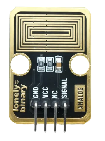
The gold rectangles are seven closed loops of copper, 0.4 mm wide, one inside the other. The soldermask is opened over exactly the traces, so the gold is bare, and the strips between them, 0.20 to 0.35 mm wide, keep their black mask.
They are not all one wire. Vias on their edges tie the outermost loop and every other one inward, four in all, to VCC. The three between them are tied to a node this book calls SENSE. So every gap on the board has a VCC loop on one side and a SENSE loop on the other.
Pick each part. Below the loops are three 0805 parts:
- R9, 1 MΩ (printed 1004), from SENSE to GND. It holds SENSE at 0 V while nothing bridges the loops.
- R11, 150 Ω (printed 1500), from SENSE to the SIGNAL pin.
- C3, 100 nF, from SIGNAL to GND, the tan one.
No current while dry
VCC reaches the four loops and nothing else. Dry, nothing joins them to anything, and the block draws no current at all. Wet, the most it can ever draw is VCC through the 1 MΩ: 3.3 µA from 3.3 V. A divider made of water works through what that current does to SIGNAL, and why the capacitor what the 100 nF is for.
When it does not work
No. The board has three passive parts and a pattern of copper. Where wet begins is a number in your sketch, which is where the wet-or-dry article puts it.
No. They are the LEGO-compatible mounting holes, 16 mm apart. The BOM lists them as U2 and they are plated, but they are on no net: water on them changes nothing.
Yes, gently. Rinse with isopropyl alcohol and let it dry; a soft brush lifts grime. Do not scrape: the gold finish is thin, and the copper under it is what a scratch exposes.
Edit this page — content/books/steam-sensor/what-is-on-it.mdx
Questions about this product
See what other owners have asked, and read their solutions.
Steam Sensor
Loading discussions…
Discuss this article
Ask about this page. The answer stays here, on the page it belongs to, for whoever hits the same wall next.