Specifications
| Type | Analog light sensor: an NPN phototransistor with a 4.7 kΩ load. More light, higher voltage on SIGNAL |
|---|---|
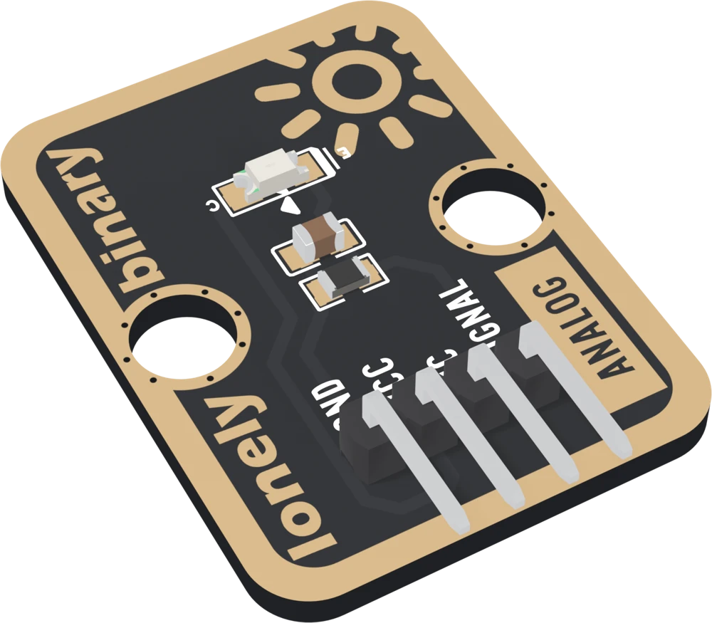
| Sensor | NEWOPTO XYC-PT21C-L1 phototransistor, a clear 1206 package (3.2 × 1.5 mm) near the top of the board. Not an LDR |
| Output | About 0.5 µA per lux through 4.7 kΩ: about 0.24 V at 100 lux for a typical part, about 0 V in the dark. Any one part within 30 % of typical |
| Ceiling | About VCC − 0.4 V: about 4.6 V from 5 V (near 1960 lux, typical) and about 2.9 V from 3.3 V (near 1230 lux). Brighter light reads the same |
| Response | 15 µs switching and a 0.47 ms filter (4.7 kΩ with 100 nF): fast enough to follow the 100 or 120 Hz ripple of many mains lamps |
| Spectrum | Peaks at 850 nm, in the near infrared; responds from 400 to 1100 nm. Not calibrated in lux |
| Supply | 3.3 V or 5 V on VCC. VCC sets the ceiling, not the reading, so use 3V3 beside an ESP32, ESP32-S3 or Pico and 5V beside an Uno |
| Current | Under 1 mA at most, at the ceiling from 5 V; tens to a couple of hundred µA in a lit room |
| Pins to wire | 3 of the 4: GND, VCC and SIGNAL. NC is connected to nothing on the board |
| Header | 4-pin right-angle male, 2.54 mm pitch: GND, VCC, NC, SIGNAL, with GND on the square pad |
| Board | 22.4 × 30.4 mm, two 4.8 mm mounting holes 16 mm apart. No LED on the board |
| In the box | 1 × TK20 block. It also ships inside the TinkerBlock kits |
What it is
A light sensor, a resistor and a capacitor. The sensor is a phototransistor: light lets a current flow through it, about half a microamp per lux for a typical part, and the 4.7 kΩ resistor turns that current into a voltage. That voltage is SIGNAL. Dark, about 0 V; a lit room, a few tenths of a volt to about a volt; bright light, up to just under VCC.
Three things about it decide how a sketch should treat it. It is fast, switching in about 15 µs, so it sees the ripple in many mains lamps and a single reading jitters; averaging over 50 ms cures that. It sees near infrared best, peaking at 850 nm, so the same brightness to your eye reads very differently under different lamps. And the number is not a unit: any one sensor can be 30 % more or less sensitive than typical. Calibrate at runtime: read the two conditions you care about and put the threshold between them.
The page this replaces called the sensor an LDR, a resistor that changes with light, and said it was slow and saw green best. None of that is this board.
VCC sets the ceiling, not the reading
The light sets the current and the resistor sets the voltage, so in a room VCC changes nothing. What VCC does set is how high SIGNAL can go: about 0.4 V under it, where bright light flattens out.
| Your board | VCC to | A lit room | Bright light | Reads up to |
|---|---|---|---|---|
| Arduino Uno | 5V | roughly 50 to 240 | about 4.6 V | about 940 of 1023 |
| ESP32, ESP32-S3 | 3V3 | roughly 180 to 1470, illustrative | about 2.9 V | about 3800 of 4095, illustrative |
| Raspberry Pi Pico | 3V3 | roughly 70 to 360 | about 2.9 V | about 900 of 1023 |
Never 5V beside a 3.3 V board: bright light would take SIGNAL towards 4.6 V. The lux and room figures are a typical part under the datasheet's light, which stops at 100 lux; above that they are the same line extended. On an ESP32, a room under about 43 lux reads 0.
Which pin is which
Parts up, header at the bottom, reading left to right:
| GND | to your board's GND | the square pad: count from here |
| VCC | to 3V3 or 5V | your board's logic voltage |
| NC | nothing | not connected on the board |
| SIGNAL | to an analog input | higher with more light |
The back prints TK20 AMBIENT LIGHT instead of pin names. Turned over, the square pad is on the right, and it is still GND. There is no LED: test it by covering the sensor and shining a torch on it.
Wiring, in three lines
- GND to your board's GND.
- VCC to 5V on an Uno, 3V3 on an ESP32, ESP32-S3 or Pico.
- SIGNAL to an analog pin: A0 on an Uno, GPIO 34 on an ESP32, GPIO 4 on an ESP32-S3, GP26 on a Pico. On an ESP32, use an ADC1 pin so Wi-Fi does not stop the reading.
Leave NC unconnected.
Example
// The analog pin SIGNAL is wired to.
// Uno: A0. ESP32: 34. ESP32-S3: 4. Pico: 26.
const int LIGHT_PIN = A0;

void setup() {
  Serial.begin(115200);
}

void loop() {
  // The mean of everything read in 50 ms: whole cycles of a
  // mains lamp's 100 or 120 Hz ripple, so the ripple cancels.
  long sum = 0;
  long n = 0;
  unsigned long start = millis();
  while (millis() - start < 50) {
    sum += analogRead(LIGHT_PIN);   // more light, higher
    n++;
  }
  Serial.println(sum / n);
  delay(200);
}import sys
import time
from machine import ADC, Pin
# The GPIO number SIGNAL is wired to. ESP32: 34. ESP32-S3: 4. Pico: 26.
adc = ADC(Pin(4))
if sys.platform == "esp32":
adc.atten(ADC.ATTN_11DB) # the full range, to about 3.1 V
while True:
total = 0
n = 0
start = time.ticks_ms()
while time.ticks_diff(time.ticks_ms(), start) < 50:
total += adc.read_u16() # more light, higher
n += 1
print(total // n)
time.sleep_ms(200)Where to start
The handbook below is ten short articles, each with a working figure. The first reading is the whole build in three wires and a few lines, and not an LDR is what the part really is.
For a light that comes on at dusk, a night light is the project. If the numbers wobble, read the flicker under room lights; if an ESP32 reads 0, reading it on an ESP32.
And before plugging it into an ESP32, VCC sets the ceiling is the one page that protects the board.
When it doesn’t work
- What kind of sensor is it?
- A phototransistor, the NEWOPTO XYC-PT21C-L1. Light lets a current through it in proportion to the light, and a 4.7 kΩ resistor turns that current into the voltage on SIGNAL. It is not an LDR, though this page used to say so, and the difference shows in its speed, the colour it sees best and what VCC does.
- What should a lit room read?
- Less than you might expect. A lit room is roughly 100 to 500 lux, which on an Uno reads roughly 50 to 240 of 1023. Covered, it reads near 0; a phone torch held close takes it to about 940, the ceiling from 5 V. Your numbers depend on the light and on the part.
- Should VCC go to 3V3 or 5V?
- To your board's logic voltage: 3V3 on an ESP32, ESP32-S3 or Pico, 5V on an Uno. In a room VCC makes no difference to the reading, but bright light takes SIGNAL up to about 0.4 V under VCC, so 5V on VCC can put about 4.6 V on a 3.3 V pin the first time the sun reaches it.
- Why does my ESP32 read 0 in a dim room?
- Its ADC reads nothing below about 0.1 V at the Arduino core's default setting, and this block gives about 0.1 V at about 43 lux for a typical part. Below that an ESP32 reads 0 while an Uno still reads a little. Shine a torch on it: if the number jumps, the block is fine.
- Why does it read so differently under different lamps?
- It is most sensitive at 850 nm, in the near infrared you cannot see. A filament or halogen bulb, or daylight, gives out plenty of infrared and reads several times higher than a white LED that looks just as bright. A TV remote makes it jump. Calibrate under the light it will live with.
- Why does the reading jitter under my ceiling light?
- Many LED and fluorescent lamps ripple at 100 or 120 times a second, and this sensor is fast enough to follow them. Average everything read over 50 ms, which is whole cycles at both rates, and the jitter goes away.