Specifications
| Receiver | Vishay TSOP18138: photodiode, amplifier, 38 kHz band-pass filter and demodulator in one three-pin package, lying flat in a steel shield |
|---|---|
| Carrier | Tuned to 38 kHz; half sensitivity about 2.7 kHz either side |
| Supply | 2.0 to 5.5 V on VCC. SIGNAL idles at VCC, so use 3V3 beside an ESP32, ESP32-S3 or Pico and 5V beside an Uno |
| Current | 0.35 mA typical at 3.3 V, 0.45 mA maximum, plus about 3 mA for the red LED while a burst arrives on 5 V |
| Output | SIGNAL is active LOW: HIGH at rest through 30 kΩ inside the chip, LOW while a 38 kHz burst arrives. Sinks up to 5 mA |
| Half angle | ±45 degrees off axis |
| Range | 26 m in Vishay's own test, in the dark with an LED at 50 mA. Two to five metres indoors with the TK16 on 5 V is a working figure |
| Indicator | Red LED from VCC into SIGNAL through 1 kΩ: lights while a burst arrives, before any code runs |
| Pins to wire | 3 of the 4: GND, VCC and SIGNAL. NC is connected to nothing on the board |
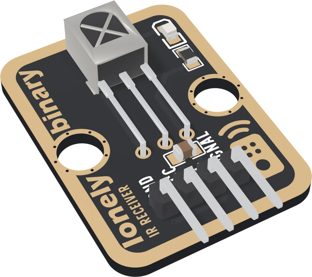
| Header | 4-pin right-angle male, 2.54 mm pitch: GND, VCC, NC, SIGNAL, with GND on the square pad |
| Board | 22.4 × 30.4 mm, two 4.8 mm mounting holes 16 mm apart |
| In the kit | The IR Remote Mastery Kit: 3 × TK15 receiver, 3 × TK16 sender and 3 × 17-button NEC remote; remote batteries (2 × AAA each) not included |
What it is
A remote does not flash a light at you. It switches an infrared LED on and off 38,000 times a second and sends its bits by turning that flicker on and off, because a bare pulse of light looks like sunlight and a 38 kHz tone does not.
The TK15 carries the part that undoes it: a Vishay TSOP18138, a photodiode, amplifier, 38 kHz filter and demodulator in one package, lying flat in a steel shield and looking out through its X-shaped window. What reaches your pin is the message with the carrier stripped off: SIGNAL is HIGH at rest and LOW while a burst arrives.
The IRremote library times those lows and hands your sketch a protocol, an address and a command. Neither number is standard: they belong to the remote that sent them.
The boxes
The TK15 comes in the IR Remote Mastery Kit with the TK16 sender: three of each and three 17-button remotes. The remotes take two AAA cells each, not included.
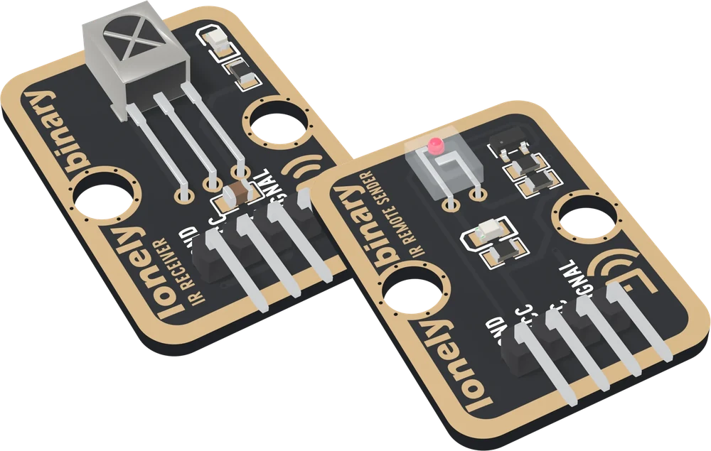
| TK15 IR Receiver | TK16 IR Sender | |
|---|---|---|
| SIGNAL is | an output your board reads | an input your board drives |
| Active | LOW, while a burst arrives | HIGH, to light the LED |
| VCC | your board's logic voltage | 5V for range; 3V3 works |
| Beam | ±45° | ±20° |
| Part | TSOP18138 | IR908-7C and an S8050 |
Which pin is which
Parts up, header at the bottom, left to right:
| GND | to your board's GND | the square pad: count from here |
| VCC | to 3V3 or 5V | your board's logic voltage |
| NC | nothing | not connected on the board |
| SIGNAL | to a digital input | LOW while a remote sends |
The back prints TK15 IR RECEIVER instead of pin names. Turned over, the square pad is on the right, and it is still GND.
Wiring, in three lines
- GND to your board's GND.
- VCC to 5V on an Uno, 3V3 on an ESP32, ESP32-S3 or Pico.
- SIGNAL to a digital pin: D2 on an Uno, GPIO 23 on an ESP32, GPIO 9 on an ESP32-S3, GP16 on a Pico.
Leave NC unconnected.
Example
#include <IRremote.hpp>   // IRremote by shirriff, z3t0 and ArminJo

// Uno: 2. ESP32: 23. ESP32-S3: 9. Pico: 16.
const int IR_RX_PIN = 2;

void setup() {
  Serial.begin(115200);
  IrReceiver.begin(IR_RX_PIN, DISABLE_LED_FEEDBACK);
}

void loop() {
  if (!IrReceiver.decode()) return;
  IRData &d = IrReceiver.decodedIRData;
  if (d.flags & IRDATA_FLAGS_IS_REPEAT) {
    Serial.println("[repeat]");        // a held button
  } else {
    Serial.print("address=0x");
    Serial.print(d.address, HEX);
    Serial.print("  command=0x");
    Serial.println(d.command, HEX);
  }
  IrReceiver.resume();    // nothing else decodes until this runs
}# mpremote mip install "github:peterhinch/micropython_ir/ir_rx"
import time
from machine import Pin
from ir_rx.nec import NEC_8
# ESP32: 23. ESP32-S3: 9. Pico: 16.
IR_RX_PIN = 9
def got(command, address, ctrl):
if command < 0: # a repeat frame
print("[repeat]")
else:
print("address=0x%02x command=0x%02x" % (address, command))
ir = NEC_8(Pin(IR_RX_PIN, Pin.IN), got)
while True:
time.sleep_ms(500)Where to start
The handbook below covers both boards and the remote, in eleven short articles, each with a working figure. Your first key code is the one to run first: every project with this block begins by finding out what your own remote sends. The carrier is the trick explains the rest of the behaviour on this page, and how far, and how wide is the honest answer about range.
When it doesn’t work
- Is this a VS1838B?
- No. It is a Vishay TSOP18138, with a documented datasheet (Vishay document 82802): a 2.0 to 5.5 V supply, a 30 kΩ pull-up inside the chip and a ±45° half angle. Most of what is written about the VS1838B does not apply.
- digitalRead always returns 1. Is it broken?
- No, that is the idle level. SIGNAL is active LOW and each low in a NEC frame lasts 560 microseconds, so an ordinary loop misses nearly all of them. The IRremote library samples the pin on a timer every 50 microseconds instead.
- Does SIGNAL need a pull-up resistor?
- No. There is a 30 kΩ pull-up inside the chip. An external pull-up changes nothing; a strong pull-down stops it working.
- Should VCC go to 3V3 or 5V?
- To your board's logic voltage: 5V on an Uno, 3V3 on an ESP32, ESP32-S3 or Pico. SIGNAL idles at whatever VCC is.
- Nothing decodes. Which end is wrong?
- Watch the red LED while you press a button. It runs into SIGNAL, so it flickers whenever the chip hears a carrier, before any code runs. No flicker: power, wiring or distance. Flicker and nothing printed: the sketch.
- My codes differ from the example.
- Expected. Codes belong to the remote that sent them. Print what your own remote sends with the key-code sketch and use those numbers.
- analogWrite stopped working on pins 3 and 11.
- On an Uno the library receives with Timer2, which drives PWM on those two pins. It is receiving that costs them. Move the output to pin 5, 6, 9 or 10.