Specifications
| Type | Digital temperature sensor: the sensor, the converter and the I2C interface are all inside the chip, so the reading arrives in degrees |
|---|---|
| Chip | UMW LM75BD, SOIC-8, a second source for NXP's LM75B with the same pins and registers |
| Range | −55 to 125 °C, the chip's rated range. The board, the header and your wiring set their own limits well before the top of it |
| Accuracy | ±2 °C from −25 to 100 °C and ±3 °C to the ends of the range, both maxima, on NXP's datasheet. UMW's datasheet for the fitted part claims ±1 °C; this page promises NXP's |
| Resolution | 0.125 °C, eleven bits, on NXP's datasheet; UMW's claims 0.0625 °C, twelve bits. Reading the two bytes as a signed number over 256 gives whichever the chip has |
| Update rate | A new reading every 100 ms (NXP) or 80 ms (UMW). Reading faster returns the last one again |
| Address | 0x48, fixed: A0, A1 and A2 are tied to GND on the board. One TK42 per I2C bus |
| Supply | 2.8 to 5.5 V on VCC. VCC goes to your board's logic supply: 5V on an Uno, 3V3 on an ESP32, an ESP32-S3 or a Pico |
| Pull-ups | 10 kΩ on SDA and on SCL to VCC, through the I2C PULL UP jumper on the back, joined as shipped |
| Clock | I2C up to 400 kHz. The sketches here use the default 100 kHz |
| OS output | The chip's thermostat pin, OS, is not connected on this board. A sketch compares the reading with a limit instead |
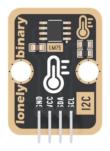
| Header | 4-pin right-angle male, 2.54 mm pitch: GND, VCC, SDA, SCL, with GND on the square pad. All four are wired |
| Board | 22.4 × 30.4 mm, two 4.8 mm mounting holes 16 mm apart. No LED |
| In the box | 1 × TK42 block, header fitted. It also ships inside the TinkerBlock kits |
What it is
A temperature sensor on two wires. The chip holds the sensor, the converter and the I2C interface, and keeps its latest reading in a register: your board asks for two bytes and gets degrees. No divider, no analog pin, no formula.
It answers at 0x48, which is fixed: the chip's address pins are wired to GND on the board. Two pull-up resistors on SDA and SCL end at VCC, by way of a jumper on the back marked I2C PULL UP. There is no LED; a chip that answers at 0x48 is the sign it is alive.
The page this replaces said the address could be strapped anywhere from 0x48 to 0x4F, quoted 9 bits and "±2 °C typical", and offered an interrupt output. On this board the address is fixed, the chip keeps 11 bits, ±2 °C is the maximum, and the output is not connected.
Wiring, in four lines
| Your board | VCC to | SDA to | SCL to |
|---|---|---|---|
| Arduino Uno | 5V | A4 | A5 |
| ESP32 | 3V3 | GPIO 21 | GPIO 22 |
| ESP32-S3 | 3V3 | GPIO 8 | GPIO 9 |
| Raspberry Pi Pico | 3V3(OUT) | GP4 | GP5 |
- GND to your board's GND.
- VCC to your board's logic supply. Never 5V beside a 3.3 V board.
- SDA to your board's SDA pin.
- SCL to your board's SCL pin.
Parts up, header at the bottom, the pins read GND, VCC, SDA, SCL from left to right, and GND is the square pad. The back prints TK42 LM75 and I2C TEMPERATURE SENSOR but no pin names; turned over, the square pad is on the right.
Three things to know
| Read it signed | the two bytes as an int16_t, over 256; a 32-bit int loses the sign |
| Step is not accuracy | it counts in eighths and may be 2 °C off |
| One per bus | 0x48 only; a second TK42 needs a second I2C bus |
Where to start
The handbook below is nine short articles. The four pins and VCC sets the bus are the ones to read before wiring. Degrees in two bytes is the one line of arithmetic, and The first reading is the sketch, for an Uno, an ESP32, an ESP32-S3 or a Pico, in Arduino and in MicroPython.
When it doesn’t work
- Should VCC go to 3V3 or 5V?
- To the voltage your board's pins run at: 5V on an Uno, 3V3 on an ESP32, an ESP32-S3 or a Pico. The pull-ups on SDA and SCL end at VCC, so 5V on VCC beside a 3.3 V board puts 5 V on its pins.
- Can I put two on one bus?
- No. The chip's three address pins are tied to GND in copper, so every TK42 is 0x48. Put the second one on a second I2C bus: every ESP32 has two, and the second is Wire1 in the Arduino core.
- Below zero it reads about 250 °C.
- The two bytes were combined in a 32-bit int, which loses the sign. Read them into an int16_t and divide by 256.0. An Uno gets away with the old code because its int is 16 bits; an ESP32 or a Pico does not.
- It reads a degree or two above room temperature.
- The chip measures its own temperature, and a microcontroller or a regulator nearby warms the board. Move it away on longer wires and give it a minute. The rest, up to 2 °C, is within what the datasheet allows.
- Where is the alert or thermostat pin?
- The chip has one, OS, and this board leaves it unconnected. Read the temperature in the sketch and switch whatever needs switching from there.