Specifications
| Type | Coin vibration motor with its driver: a MOSFET switch, a 3.3 V regulator, a flyback diode and an indicator LED. HIGH on SIGNAL buzzes, LOW stops |
|---|---|
| Motor | LEADER LCM1027A2445F, Ø10 × 2.7 mm, laid flat on its own tape. Rated 3.0 V, for 2.7 to 3.3 V; 13500 ± 3500 rpm at 3.0 V |
| Motor current | 80 mA max running and 120 mA max starting (datasheet); about 54 mA typical at 3.3 V. None of it flows through SIGNAL |
| Driver | AO3400A N-channel MOSFET between the motor and GND. Gate threshold 0.7 to 1.4 V, so 3.3 V and 5 V logic both switch it fully on |
| SIGNAL | The MOSFET's gate with 10 kΩ to GND: 0.33 mA from a 3.3 V pin, 0.5 mA from 5 V. Off when unconnected. PWM sets the strength |
| Supply | 5V or 3V3 on VCC, on any board: VCC only feeds the 3.3 V regulator and never reaches SIGNAL, so 5V is safe beside a 3.3 V board. Either gives the motor about 3.3 V |
| Motor voltage | About 3.3 V from the XC6206P332MR regulator, measured on a board with 5 V on VCC and with 3.3 V on VCC |
| Start | A stopped motor is guaranteed to start from 2.3 V: about 178 of 255 from 5V on VCC. Below that, kick it at 255 first |
| Protection | SS14 Schottky diode across the motor for the switch-off kick, and 100 nF across it for noise. Nothing to add |
| Pins to wire | 3 of the 4: GND, VCC and SIGNAL. NC is connected to nothing on the board |
| Header | 4-pin right-angle male, 2.54 mm pitch: GND, VCC, NC, SIGNAL, with GND on the square pad |
| Board | 22.4 × 30.4 mm, two 4.8 mm mounting holes 16 mm apart. The LED lights while the motor is driven |
| In the box | 1 × TK30 block. It also ships inside the TinkerBlock kits |
What it is
A coin vibration motor and the circuit that drives it. The motor is 10 mm across, lies flat on the board on its own tape, and spins an off-centre weight at about fifteen thousand rpm. The rest of the board is its driver: a MOSFET that switches it, a 10 kΩ that keeps it off when nothing drives SIGNAL, a 3.3 V regulator that feeds it, a diode that takes the kick when it stops, and an LED that lights while it is driven.
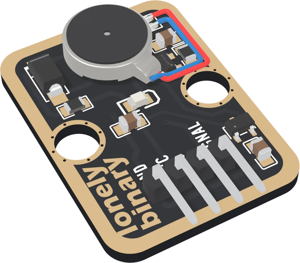
SIGNAL HIGH closes the MOSFET and the motor runs; LOW opens it and the motor
coasts to a stop. analogWrite sets the strength, down to about 178 of 255
from rest; below that, start it at full power and then drop. The motor's
current, about 54 mA running and up to 120 mA starting, never passes through
your board's pin, which only drives the MOSFET's gate.
The page this replaces left the regulator out, and suggested a separate supply and a large capacitor for the motor. On this board the motor already has its own supply, the regulator, and VCC can be 5V or 3V3 on every board.
VCC feeds the regulator, and nothing else
| Your board | VCC to | SIGNAL to | The motor gets |
|---|---|---|---|
| Arduino Uno | 5V | D9 | 3.3 V |
| ESP32 | 5V | GPIO 4 | 3.3 V |
| ESP32-S3 | 5V | GPIO 4 | 3.3 V |
| Raspberry Pi Pico | VBUS | GP15 | 3.3 V |
5V on VCC beside a 3.3 V board is safe here: VCC reaches only the regulator and its capacitor, and SIGNAL reaches only the MOSFET's gate. The motor is a 3.0 V part rated for 2.7 to 3.3 V, and the regulator holds it at 3.3 V. VCC on 3V3 gives it about 3.3 V too, measured on a board, so on a battery with no 5 V pin, or whenever 3V3 is nearer, use 3V3.
Which pin is which
Parts up, header at the bottom, reading left to right:
| GND | to your board's GND | the square pad: count from here |
| VCC | to 5V (VBUS on a Pico) | feeds the 3.3 V regulator |
| NC | nothing | not connected on the board |
| SIGNAL | to a digital or PWM pin | HIGH buzzes, LOW stops |
The back prints TK30 VIBRATION MOTOR and, along the bottom, VIBRATES WHEN THE INPUT IS HIGH, STOPS WHEN IT'S LOW, but no pin names. Turned over, the square pad is on the right, and it is still GND.
Wiring, in three lines
- GND to your board's GND.
- VCC to 5V: an Uno's 5V, the 5V pin of an ESP32 or ESP32-S3 board on USB, or a Pico's VBUS. 3V3 works as well: the motor gets the same 3.3 V.
- SIGNAL to a PWM pin: D9 on an Uno, GPIO 4 on an ESP32 or ESP32-S3, GP15 on a Pico.
Leave NC unconnected.
Example
// A PWM pin. Uno: 9. ESP32: 4. ESP32-S3: 4. Pico: 15.
const int MOTOR_PIN = 9;
const int KICK_MS = 50;   // full power first, so low levels start

void buzz(int level, int ms) {
  analogWrite(MOTOR_PIN, 255);      // kick: sure to start
  delay(KICK_MS);
  analogWrite(MOTOR_PIN, level);    // then the strength you want
  delay(ms);
  analogWrite(MOTOR_PIN, 0);
}

void setup() {
  pinMode(MOTOR_PIN, OUTPUT);
}

void loop() {
  buzz(255, 300);   // strong
  delay(700);
  buzz(150, 300);   // gentler
  delay(700);
}import time
from machine import Pin, PWM
# A PWM pin. ESP32: 4. ESP32-S3: 4. Pico: 15.
motor = PWM(Pin(4), freq=1000)
motor.duty_u16(0)
KICK_MS = 50 # full power first, so low levels start
def buzz(level, ms):
motor.duty_u16(65535) # kick: sure to start
time.sleep_ms(KICK_MS)
motor.duty_u16(level * 257) # then the strength you want
time.sleep_ms(ms)
motor.duty_u16(0)
while True:
buzz(255, 300) # strong
time.sleep_ms(700)
buzz(150, 300) # gentler
time.sleep_ms(700)Where to start
The handbook below is ten short articles, each with a working figure. The first buzz is the whole build in three wires and a few lines, and why VCC can be 5V is the one page that explains the wiring.
For strength, read strength is a duty cycle and a kick to start. For haptic feedback on a button, patterns you can feel. If it will not buzz, when it does not buzz.
When it doesn’t work
- Do I need a transistor, a diode or a capacitor with it?
- No. The board has the MOSFET that carries the motor's current, the diode that takes the kick when it stops, the capacitors, and a regulator that feeds the motor. Three wires to your board are the whole circuit.
- Should VCC go to 3V3 or 5V?
- Either, whichever is handy. VCC only feeds the block's 3.3 V regulator, and nothing connects it to SIGNAL, so 5V cannot reach a 3.3 V pin. Measured on a board, the motor gets about 3.3 V from 5V and about 3.3 V from 3V3. This page wires 5V (VBUS on a Pico), which takes the motor's current off USB rather than your board's own 3.3 V regulator.
- Low PWM values do nothing.
- Below about 2.3 V, roughly 178 of 255, a stopped motor is not guaranteed to start. Give it 255 for about 50 ms, then drop to the level you want: a turning motor keeps going at lower levels than it starts at.
- My board resets when the motor starts.
- The motor asks for up to 120 mA as it starts. With VCC on 3V3 that comes out of the same small regulator that feeds your microcontroller. Move VCC to 5V, or VBUS on a Pico, so the block's own regulator takes it. There is no separate motor supply to add.
- The LED lights but it does not buzz.
- The LED lights when the MOSFET closes, and its current does not pass through the motor. So SIGNAL and power are fine; look at the motor's thin red and blue leads where they meet their pads.
- It buzzes but weakly.
- Check VCC is on 5V rather than 3V3, then how it is mounted. Loose on a desk much of the shake goes into lifting the board; fixed firmly to what it should shake, it is obvious.