Specifications
| Type | Two high-brightness LEDs |
|---|---|
| Control | Digital on/off, or PWM |
| Series resistors | Fitted on the module |
| Supply voltage | 3.3 V or 5 V |
| Note | Draws meaningfully more current than an indicator LED |
What it is
Two LEDs chosen for output rather than indication, with their resistors on the board. Bright enough to light a scene rather than to say that something happened.
The current is the part to plan for. An indicator LED is a couple of milliamps; these are tens, and two of them at once from a 3.3 V regulator that is also running a radio is enough to cause a visible brownout. Drive them from the 5 V rail where you can, and if you are pulsing them for a camera flash, add a capacitor near the module so the burst comes out of that rather than out of your supply.
PWM dims them, and unlike a vibration motor they dim smoothly all the way down — though your eye is logarithmic, so the bottom quarter of the PWM range covers most of the perceived change.
Do not look into them at close range.
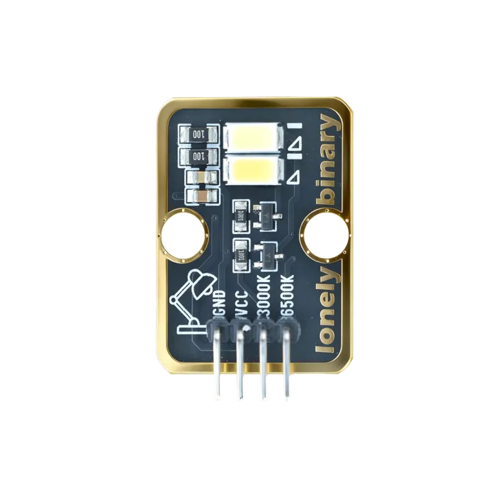
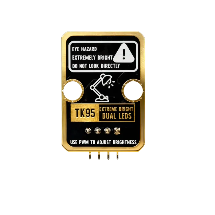
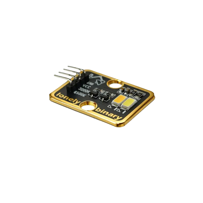
Pinout
- GND (negative): Like the negative terminal (-) of a battery, connect to the control board's GND
- VCC (positive): Like the positive terminal (+) of a battery, connect to the control board's 3.3V or 5V (this module supports both 3.3V and 5V)
- 3000K (warm white control): Pin to control 3000K warm white LED, connect to the control board's PWM pin (e.g. Arduino D3 or Pico GPIO 1)
- 6500K (cool white control): Pin to control 6500K cool white LED, connect to the control board's PWM pin (e.g. Arduino D5 or Pico GPIO 2)
Wiring
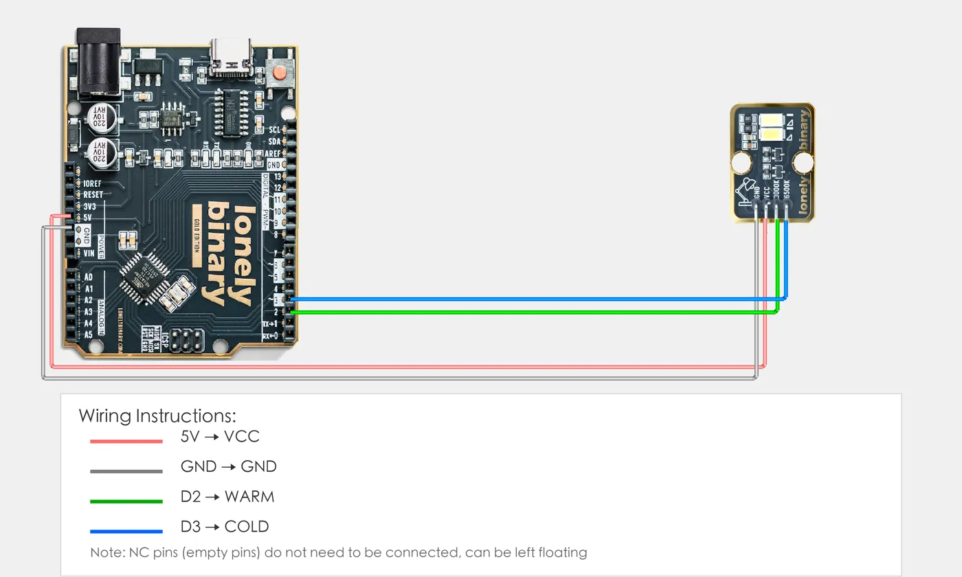
- GND → Control board GND
- VCC → Control board 3.3V or 5V
- 3000K → Control board PWM pin (use the pin defined in your program)
- 6500K → Control board PWM pin (use the pin defined in your program)
Example
// Pin number: change these to match your wiring
#define WARM_PIN 2   // Arduino PWM pin connected to 3000K (e.g. D3)
#define COLD_PIN 3   // Arduino PWM pin connected to 6500K (e.g. D5)

void setup() {
  // Set LED pins as output mode
  pinMode(WARM_PIN, OUTPUT);
  pinMode(COLD_PIN, OUTPUT);

  // Start serial for debugging (9600 baud)
  Serial.begin(9600);
}

void loop() {
  // Warm white (3000K brightest, 6500K off)
  analogWrite(WARM_PIN, 255);   // Warm white brightest
  analogWrite(COLD_PIN, 0);      // Cool white off
  Serial.println("Warm white");
  delay(2000);

  // Cool white (3000K off, 6500K brightest)
  analogWrite(WARM_PIN, 0);
  analogWrite(COLD_PIN, 255);
  Serial.println("Cool white");
  delay(2000);

  // Mixed light (both LEDs on, color temperature in middle)
  analogWrite(WARM_PIN, 128);   // Warm white medium brightness
  analogWrite(COLD_PIN, 128);    // Cool white medium brightness
  Serial.println("Mixed light");
  delay(2000);
}# Import required modules
from machine import Pin, PWM # GPIO control and PWM
import time # For delay (time.sleep)
# Pin number: change these to match your wiring
WARM_PIN = 1 # GPIO connected to 3000K (e.g. GPIO 1, must be PWM-capable pin)
COLD_PIN = 2 # GPIO connected to 6500K (e.g. GPIO 2)
# Create PWM objects
warm = PWM(Pin(WARM_PIN))
cold = PWM(Pin(COLD_PIN))
# Set PWM frequency (1000 Hz)
warm.freq(1000)
cold.freq(1000)
# Main loop: runs forever
while True:
# Warm white (3000K brightest, 6500K off)
warm.duty_u16(65535) # Warm white brightest (65535 is max value)
cold.duty_u16(0) # Cool white off
print("Warm white")
time.sleep(2)
# Cool white (3000K off, 6500K brightest)
warm.duty_u16(0)
cold.duty_u16(65535)
print("Cool white")
time.sleep(2)
# Mixed light (both LEDs on, color temperature in middle)
warm.duty_u16(32767) # Warm white medium brightness
cold.duty_u16(32767) # Cool white medium brightness
print("Mixed light")
time.sleep(2)When it doesn’t work
- The board browns out or resets when both come on.
- Current. Move them to the 5 V rail, add a 100 µF capacitor nearby, or drive one at a time.
- Dimming looks wrong at low levels.
- Perception is logarithmic while PWM is linear. Square the duty cycle for a curve that looks even.
- They get warm.
- At full output that is expected. If they are hot rather than warm, you are running from a higher voltage than the resistors were sized for.