Specifications
| Type | I2C serial EEPROM: memory that keeps its contents with the power off, rewritten a byte at a time |
|---|---|
| Chip | HXY AT24C128, SOIC-8. 128 Kbit, organised as 16,384 bytes, addressed with two bytes |
| Memory | 16,384 bytes, in 256 pages of 64 bytes. A write stays inside its page and wraps to the page's start |
| Address | 0x50, fixed: A0, A1 and A2 are tied to GND on the board. One TK31 per bus |
| Supply | 2.2 to 5.5 V on VCC. VCC goes to your board's logic supply: 5V on an Uno, 3V3 on an ESP32, an ESP32-S3 or a Pico |
| Pull-ups | 10 kΩ on SDA and on SCL to VCC, through the I2C PULL-UP jumper on the back, joined as shipped |
| Write time | 5 ms max per write, one byte or a whole page. The chip does not answer while it writes |
| Endurance | 1,000,000 writes per byte (25 °C, 5 V, datasheet); 40-year data retention. Reads cost nothing |
| Clock | Up to 400 kHz from 2.2 V and 1 MHz from 2.5 V. The sketches here use the default 100 kHz |
| Write protect | WP is tied to GND on the board: writing is always allowed |
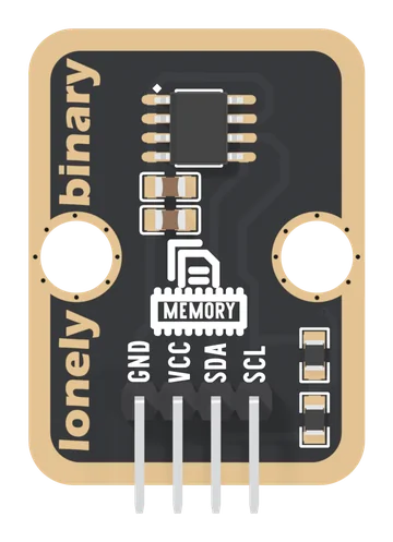
| Header | 4-pin right-angle male, 2.54 mm pitch: GND, VCC, SDA, SCL, with GND on the square pad. All four are wired |
| Board | 22.4 × 30.4 mm, two 4.8 mm mounting holes 16 mm apart. No LED |
| In the box | 1 × TK31 block. It also ships inside the TinkerBlock kits |
What it is
A memory chip on two wires. Write a byte, pull the power, come back a year later, and the byte is still there. The chip is an AT24C128: 16,384 bytes, each rewritable about a million times and kept for 40 years with no power.
It talks I2C at address 0x50, which is fixed: the chip's address pins are wired to GND on the board. Two pull-up resistors on SDA and SCL end at VCC, by way of a jumper on the back marked I2C PULL-UP. There is no LED; a scan that finds 0x50 is the sign it is alive.
The page this replaces said the address could be moved to 0x51 to 0x57. On this board it cannot. It also left out the rule that decides the wiring: VCC sets the voltage on SDA and SCL, so VCC goes to your board's logic supply.
Wiring, in four lines
| Your board | VCC to | SDA to | SCL to |
|---|---|---|---|
| Arduino Uno | 5V | A4 | A5 |
| ESP32 | 3V3 | GPIO 21 | GPIO 22 |
| ESP32-S3 | 3V3 | GPIO 8 | GPIO 9 |
| Raspberry Pi Pico | 3V3(OUT) | GP4 | GP5 |
- GND to your board's GND.
- VCC to your board's logic supply. Never 5V beside a 3.3 V board.
- SDA to your board's SDA pin.
- SCL to your board's SCL pin.
Parts up, header at the bottom, the pins read GND, VCC, SDA, SCL from left to right, and GND is the square pad. The back prints TK31 EEPROM MEMORY and NON-VOLATILE MEMORY but no pin names; turned over, the square pad is on the right.
Four rules
| Wait after a write | up to 5 ms, during which the chip answers nobody |
| Stay inside a page | a write that crosses a multiple of 64 wraps and overwrites |
| Two address bytes | high then low; libraries for small chips send one |
| Write on change | a million writes a byte is 28 hours at ten a second |
Example
#include <Wire.h>

const int EEPROM_ADDR = 0x50;   // fixed on the TK31

void writeByte(uint16_t at, uint8_t value) {
  Wire.beginTransmission(EEPROM_ADDR);
  Wire.write((uint8_t)(at >> 8));     // address, high byte
  Wire.write((uint8_t)(at & 0xFF));   // then low byte
  Wire.write(value);
  Wire.endTransmission();
  delay(5);                           // the chip is writing
}

int readByte(uint16_t at) {
  Wire.beginTransmission(EEPROM_ADDR);
  Wire.write((uint8_t)(at >> 8));
  Wire.write((uint8_t)(at & 0xFF));
  Wire.endTransmission(false);
  Wire.requestFrom(EEPROM_ADDR, 1);
  return Wire.available() ? Wire.read() : -1;
}

void setup() {
  Serial.begin(115200);
  Wire.begin();                       // the board's default I2C pins
  writeByte(0, 123);
  Serial.println(readByte(0));        // 123, before and after power-off
}

void loop() {
}import time
from machine import I2C, Pin
# SDA, SCL. ESP32: 21, 22. ESP32-S3: 8, 9. Pico: 4, 5.
i2c = I2C(0, sda=Pin(21), scl=Pin(22), freq=100_000)
EEPROM = 0x50 # fixed on the TK31
i2c.writeto_mem(EEPROM, 0, bytes([123]), addrsize=16)
time.sleep_ms(5) # the chip is writing
print(i2c.readfrom_mem(EEPROM, 0, 1, addrsize=16)[0])Where to start
The handbook below is ten short articles, each with a working figure. The first byte is the whole build in four wires, and VCC sets the bus is the one page that explains the wiring.
For more than one byte at a time, read five milliseconds a write and sixty-four-byte pages. Before you save anything in a loop, a million writes. If the chip will not answer, when it does not answer.
When it doesn’t work
- Should VCC go to 3V3 or 5V?
- To the voltage your board's pins run at: 5V on an Uno, 3V3 on an ESP32, an ESP32-S3 or a Pico. The pull-ups on SDA and SCL end at VCC, so 5V on VCC beside a 3.3 V board puts 5 V on its pins.
- Can I change the address?
- No. The chip's three address pins are tied to GND in copper, so it is 0x50. That also means two TK31s cannot share one I2C bus.
- Values come back wrong, or as 255.
- A read straight after a write reaches a chip that is still writing, for up to 5 ms, and it does not answer. Wait with delay(5), or poll until it acknowledges. If every byte is 255, check the sketch sends two address bytes: libraries for smaller chips send one.
- Long text comes back scrambled.
- A write crossed a 64-byte page edge and wrapped to the start of the same page. Cut every write at multiples of 64, and at 30 bytes or fewer on an Uno, whose Wire library holds 32 bytes per transmission.
- It worked for a week, then one byte went bad.
- Wear. Each byte takes about a million writes, which a sketch writing ten times a second uses up in about 28 hours. Write a value only when it changes, and move it to a fresh address.
- Is this what the Arduino EEPROM library uses?
- No. EEPROM.h reads the memory inside your microcontroller. The TK31 is a separate chip on the I2C bus, reached with Wire, or with readfrom_mem and writeto_mem in MicroPython.