Specifications
| Type | Latching switch input block, active high: press on, press again off |
|---|---|
| Switch | 12 × 12 mm self-locking push switch, ON–OFF single pole, 5.4 mm button. Its top stands 9 mm above the board |
| Switch rating | DC 30 V 1 A, contact resistance 200 mΩ or less, at least 50,000 cycles, from the switch's drawing |
| Operating force | 700 ± 100 gf, from the switch's drawing: a firm press |
| Pull-down | 10 kΩ from SIGNAL to GND, fitted. Off reads LOW, on reads HIGH |
| Indicator | Red LED on SIGNAL through 1 kΩ: lit whenever the switch is on and VCC is connected |
| Signal level | SIGNAL equals VCC when on, so VCC sets it: 3V3 beside a 3.3 V board, 5V on an Uno |
| Current | None with the switch off. About 3.5 mA from 5 V and 1.6 mA from 3.3 V when on, worked out from the parts |
| Pins to wire | 3 of the 4: GND, VCC and SIGNAL. NC is connected to nothing on the board |
| Header | 4-pin right-angle male, 2.54 mm pitch: GND, VCC, NC, SIGNAL, with GND on the square pad |
| Board | 22.4 × 30.4 mm, two 4.8 mm mounting holes 16 mm apart |
| In the box | 1 × TK05 block. It also ships inside the TinkerBlock kits |
What it is
A push switch that stays where you leave it. Press it once and it latches on; press it again and it goes off. SIGNAL is HIGH while it is on and LOW while it is off, so your sketch reads a level, a position, rather than catching a press.
Because the state is held by a mechanical latch, it survives anything short of
a press: a reset, a crash, the USB cable coming out. A sketch that reads it in
setup() starts in the state it was left in. The trade is that software can
read it and never change it, so it suits choices a person makes and leaves
made, such as a mode.
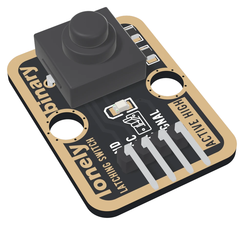
What is on the board
Three parts besides the switch, all on one wire. A 10 kΩ pull-down from SIGNAL to GND holds it at 0 V while the switch is open. The switch joins SIGNAL to VCC when it is on. A red LED with a 1 kΩ resistor hangs off SIGNAL, so it lights exactly when the switch is on. It shows the switch's position, not your sketch's.
VCC goes to the switch and to nothing else, so with the switch on, SIGNAL is VCC. That makes VCC the one pin to wire by your board: 3V3 beside an ESP32, an ESP32-S3 or a Pico, 5V on an Uno.
Which pin is which
Switch side up, header at the bottom, reading left to right:
| GND | to your board's GND | the square pad: count from here |
| VCC | to 3V3, or 5V on an Uno | SIGNAL's voltage when on |
| NC | nothing | not connected on the board |
| SIGNAL | to a digital input | HIGH when the switch is on |
The back prints TK05 LATCHING BUTTON and PRESS TO TURN ON, PRESS AGAIN TO TURN OFF instead of pin names. Turned over, the square pad is on the right, and it is still GND.
Wiring, in three lines
- GND to your board's GND.
- VCC to 3V3 on an ESP32, ESP32-S3 or Pico; to 5V on an Uno.
- SIGNAL to a digital input: D2 on an Uno, GPIO 25 on an ESP32, GPIO 4 on an ESP32-S3, GP15 on a Pico.
Leave NC unconnected. Set the pin as a plain input; the pull-down is on the board.
Example
// The GPIO number SIGNAL is wired to.
// Uno: 2. ESP32: 25. ESP32-S3: 4. Pico: 15.
const int SWITCH_PIN = 4;

void setup() {
  Serial.begin(115200);
  pinMode(SWITCH_PIN, INPUT);   // the board's pull-down holds it LOW
}

void loop() {
  if (digitalRead(SWITCH_PIN) == HIGH) {
    Serial.println("ON");       // latched: SIGNAL is VCC
  } else {
    Serial.println("OFF");
  }
  delay(500);
}from machine import Pin
import time
# The GPIO number SIGNAL is wired to. ESP32: 25. ESP32-S3: 4. Pico: 15.
switch = Pin(4, Pin.IN) # no pull: the board's pull-down holds it LOW
while True:
print("ON" if switch.value() else "OFF")
time.sleep(0.5)Where to start
The handbook below is nine short articles, each with a working figure. The first read is the whole build in three wires and a dozen lines.
If you only read one, read which supply to use. VCC is the one wire on this block that has to match your board, and getting it wrong looks like it works.
And for what makes this block different from a push button, surviving a reset turns the latch into a mode switch that a reset cannot move.
When it doesn’t work
- It reads LOW whatever I do.
- Look at the red LED. If it never lights, VCC is not wired: the switch connects SIGNAL to VCC, and with no VCC it connects it to nothing, so the pull-down keeps it LOW. If the LED lights and the sketch still reads LOW, SIGNAL is on a different pin from the one the sketch reads.
- Should I use INPUT_PULLUP?
- No, use INPUT. The block has a 10 kΩ pull-down fitted, so SIGNAL is held at 0 V with the switch off and pulled to VCC with it on. An internal pull-up only fights the pull-down. In MicroPython, Pin.IN with no pull argument.
- Can I power it from 5V on an ESP32 or a Pico?
- No. When the switch is on, SIGNAL is VCC, so a 5 V supply puts 5 V on a pin rated for 3.3 V. It will appear to work, which is the problem. Wire VCC to 3V3 on an ESP32, ESP32-S3 or Pico, and to 5V on an Uno.
- Does it need debouncing?
- Only if the sketch counts changes. Like any mechanical contact it bounces for a moment at each press, usually a few milliseconds; nobody has measured this one. A sketch that reads the level never notices. One that acts on each change should believe a new level only once it has held, 20 ms in the handbook's sketches.
- The state is still on after a reset. Is that right?
- Yes, and it is the reason to choose this block. The switch is a mechanical latch, so a reset or a power cut cannot move it. Read it in setup() and the sketch comes back in the state it was left in. If the program must be able to change the state itself, use the TK04 push button and a variable.
- What is the NC pin for?
- Nothing on this board. It is in no net at all. Every TinkerBlock block has the same four-pin header so the same cable fits all of them, and this block needs three of the four.