Specifications
| Type | Analog temperature sensor: an NTC thermistor in a voltage divider |
|---|---|
| Thermistor | 10 kΩ at 25 °C, ±1 %, B = 3950 K (Sunlord SDNT2012X103F3950FTF, 0805; values read from the part number) |
| Divider | 10 kΩ fixed from VCC to SIGNAL, thermistor from SIGNAL to GND, 100 nF across it. SIGNAL is half of VCC at 25 °C and falls as it warms |
| Supply | 3.3 V or 5 V on VCC. SIGNAL is a fraction of VCC, so use 3V3 beside an ESP32, ESP32-S3 or Pico and 5V beside an Uno |
| Pins to wire | 3 of the 4: GND, VCC and SIGNAL. NC is connected to nothing on the board |
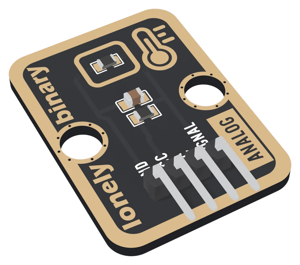
| Header | 4-pin right-angle male, 2.54 mm pitch: GND, VCC, NC, SIGNAL, with GND on the square pad |
| Signal | Analog voltage, to an analog pin: A0 on an Uno, an ADC1 pin on an ESP32 or ESP32-S3, GP26 on a Pico |
| Current | 0.5 mA at most from 5 V; under 1 mW in the thermistor, too little to warm it measurably next to the board it is plugged into |
| Board | 22.4 × 30.4 mm, two 4.8 mm mounting holes 16 mm apart |
| In the box | 1 × TK12 block. It also ships inside the TinkerBlock kits |
What it is
A thermistor, a resistor whose resistance falls as it warms, in a divider with a fixed 10 kΩ resistor. At 25 °C the thermistor is 10 kΩ too, so SIGNAL is exactly half of VCC. Warmer, SIGNAL falls; colder, it rises. The front of the board says ANALOG, and the back says RESISTANCE DECREASES AS TEMPERATURE RISES.
Your board reads SIGNAL as a voltage. Turning that into degrees is arithmetic
the sketch does itself, in two steps: back to the thermistor's resistance
through the divider, then to a temperature through the B equation, using the
10 kΩ and B = 3950 from the thermistor's part number. Neither step is a
straight line, which is why map() gets it wrong away from the two points it
is given.
VCC is what SIGNAL is a fraction of
| Your board | VCC to | SIGNAL at 25 °C | What cancels |
|---|---|---|---|
| Arduino Uno | 5V | 2.50 V | VCC: the ADC measures against it too |
| Raspberry Pi Pico | 3V3 | 1.65 V | VCC, nearly: the ADC uses the same 3.3 V |
| ESP32, ESP32-S3 | 3V3 | 1.65 V | nothing: the sketch assumes 3.3 V |
On an ESP32 read analogReadMilliVolts on an ADC1 pin. Its ADC reads to about
3.1 V at the default setting, so below about −25 °C the reading stops
falling.
Which pin is which
Component side up, header at the bottom, reading left to right:
| GND | to your board's GND | the square pad: count from here |
| VCC | to 3V3 or 5V | your board's logic voltage |
| NC | nothing | not connected on the board |
| SIGNAL | to an analog pin | falls as it warms |
The back prints TK12 NTC THERMISTOR instead of pin names. Turned over, the square pad is on the right, and it is still GND.
Wiring, in three lines
- GND to your board's GND.
- VCC to 5V on an Uno, 3V3 on an ESP32, ESP32-S3 or Pico.
- SIGNAL to an analog pin: A0 on an Uno, GPIO 34 on an ESP32, GPIO 4 on an ESP32-S3, GP26 on a Pico.
Leave NC unconnected.
Example
#include <math.h>

// Uno: A0. ESP32: 34. ESP32-S3: 4. Pico: 26.
const int SENSOR_PIN = A0;

void setup() {
  Serial.begin(115200);
}

void loop() {
#if defined(ARDUINO_ARCH_ESP32)
  float mv = analogReadMilliVolts(SENSOR_PIN);     // own reference
  float r = 10000.0 * mv / (3300.0 - mv);          // VCC taken as 3.3 V
#else
  float n = analogRead(SENSOR_PIN);                // a fraction of VCC
  float r = 10000.0 * n / (1023.0 - n);
#endif
  float c = 1.0 / (1.0 / 298.15 + log(r / 10000.0) / 3950.0) - 273.15;
  Serial.print(c, 1);
  Serial.println(" C");
  delay(1000);
}import math, sys, time
from machine import ADC, Pin
# ESP32: 34. ESP32-S3: 4. Pico: 26.
adc = ADC(Pin(4))
ESP = sys.platform == "esp32"
if ESP:
adc.atten(ADC.ATTN_11DB) # to about 3.1 V
while True:
if ESP:
ratio = adc.read_uv() / 1000000 / 3.3 # VCC taken as 3.3 V
else:
ratio = adc.read_u16() / 65535 # a fraction of VCC
r = 10000 * ratio / (1 - ratio)
c = 1 / (1 / 298.15 + math.log(r / 10000) / 3950) - 273.15
print("%.1f C" % c)
time.sleep(1)This short version does not guard against a missing wire. The handbook's sketches do, and average 32 readings for a steadier number.
Where to start
The handbook below is twelve short articles, each with a working figure. The first reading is the wiring and a count; counts to degrees is the arithmetic.
On an ESP32, read reading it on an ESP32 first. And before trusting the second decimal place, how far to trust it.
When it doesn’t work
- Does SIGNAL go up or down when it gets warmer?
- Down. The thermistor is the lower half of the divider, from SIGNAL to GND. Warmer, its resistance falls and SIGNAL drops: half of VCC at 25 °C, less above, more below. The back of the board says RESISTANCE DECREASES AS TEMPERATURE RISES.
- How do I turn the reading into degrees?
- Two lines. The thermistor's resistance is 10000 × n / (1023 − n) for an Uno's count n. Then 1/T = 1/298.15 + ln(R / 10000) / 3950, with T in kelvin. A straight map() is right at two temperatures and wrong everywhere else.
- Should VCC go to 3V3 or 5V?
- To your board's logic voltage: 5V on an Uno, 3V3 on an ESP32, ESP32-S3 or Pico. SIGNAL is always a fraction of VCC, so this keeps it inside the pin's range.
- Why does my ESP32 read a degree or so off?
- Its ADC measures against its own reference, not VCC, so the sketch has to assume VCC is 3.3 V. Each per cent the 3V3 rail is off moves the answer by about half a degree near 25 °C. Measure the 3V3 pin and put the value in the sketch. Use analogReadMilliVolts and an ADC1 pin.
- How accurate is it?
- The ±1 % parts alone allow about half a degree either way near 25 °C and more far from it; the B model and the ADC add to that. Around a degree near room temperature is a fair expectation, and a one-point calibration against a trusted thermometer improves it.
- It reads a few degrees high.
- It is measuring what it is plugged into. A regulator, a USB chip or an ESP32 running Wi-Fi is warmer than the room. Put the block on a cable a few centimetres away. The current through the thermistor itself is under a milliwatt and is not the cause.