Specifications
| Type | Piezo-ceramic sensor |
|---|---|
| Output | Analog, proportional to impact |
| Power | Generates its own signal; the module conditions it |
| Supply voltage | 3.3 V or 5 V for the conditioning circuit |
What it is
A piezoelectric disc produces a voltage when it is deformed. Tap it and you get a spike; the harder the tap, the bigger the spike.
That amplitude is what separates it from TK28, the knock switch. TK28 tells you something happened. This tells you roughly how hard, which is enough to distinguish a deliberate knock from a door closing.
Two cautions. Unloaded, a piezo can generate tens of volts on a sharp impact — the module's conditioning network clamps that, and a bare element wired straight to an ADC pin does not. And the output rings after the impact: one tap produces a decaying oscillation over several milliseconds, so take the peak of a short window rather than a single sample.
The same element run backwards is a passive buzzer, which is exactly what TK37 is.
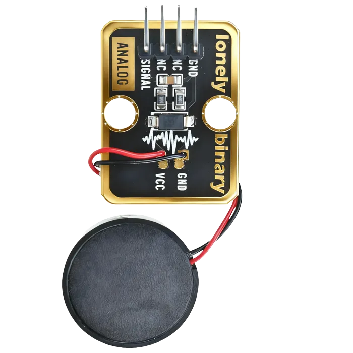
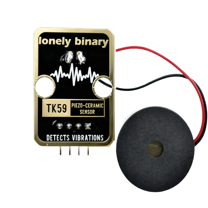
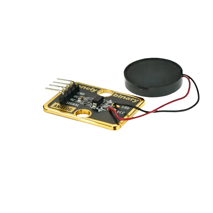
Pinout
- GND (negative): Like the negative terminal (-) of a battery, connect to the control board's GND
- VCC (positive): Like the positive terminal (+) of a battery, connect to the control board's 3.3V or 5V (this module supports both 3.3V and 5V)
- NC (no connection): No actual circuit connection, included for unified interface, can be left unconnected
- SIGNAL (signal output): Pressure detection output pin, connect to the control board's analog input pin (e.g. Arduino A0 or Pico GPIO 26)
- Outputs voltage signal when pressure is applied
- Higher pressure results in higher output voltage
Wiring
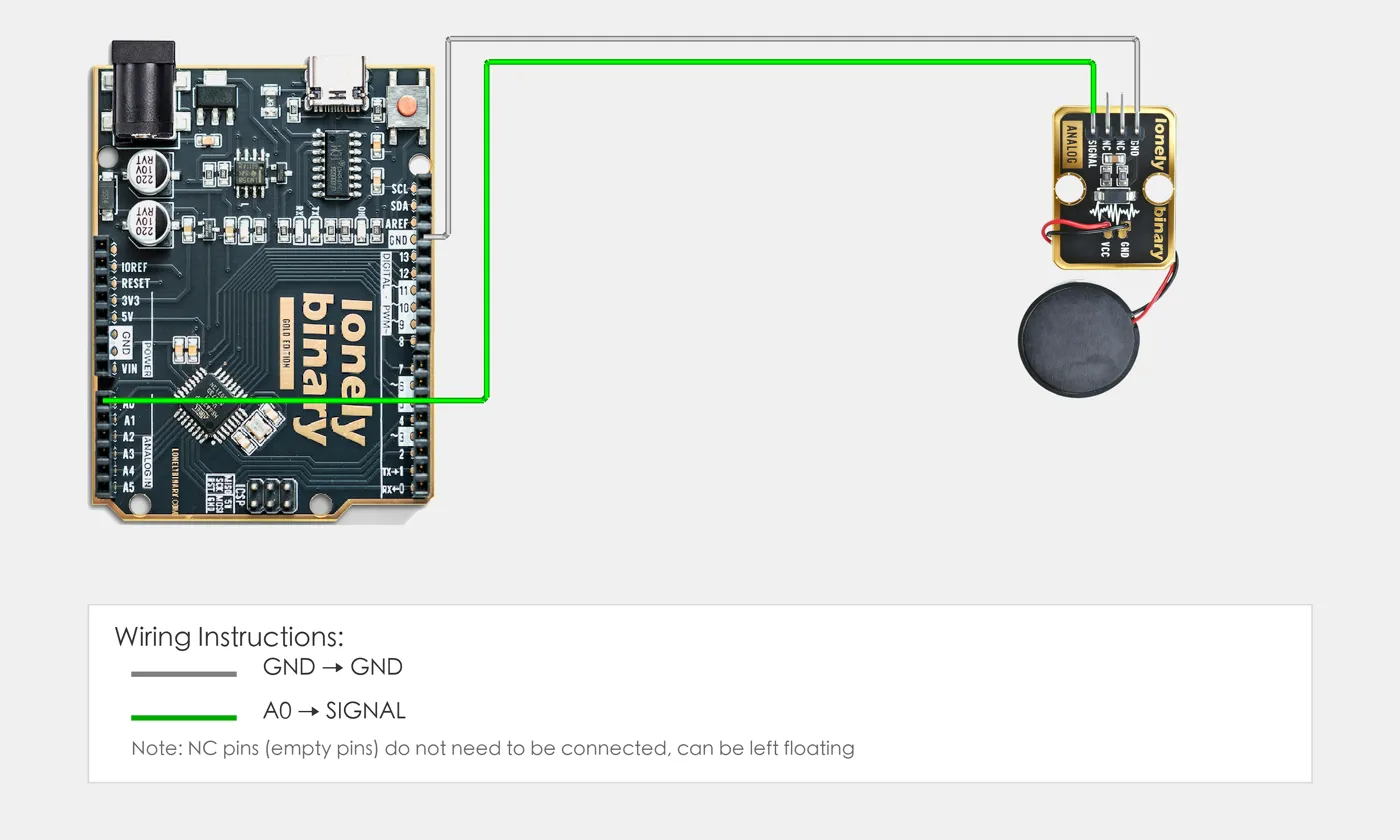
- GND → Control board GND
- VCC → Control board 3.3V or 5V
- SIGNAL → Control board analog input pin (use the pin defined in your program)
Example
// Pin number: change this to match your wiring
#define PIEZO_PIN A0  // Arduino analog input pin connected to SIGNAL (e.g. A0)

void setup() {
  // Initialize pin mode
  pinMode(PIEZO_PIN, INPUT);   // Set piezoelectric sensor pin as input (to read analog value)

  // Start serial for debugging (9600 baud)
  Serial.begin(9600);

  Serial.println("Piezoelectric sensor program started");
  Serial.println("Read pressure intensity value and output via serial");
}

void loop() {
  // Read piezoelectric sensor analog value (0-1023)
  int sensorValue = analogRead(PIEZO_PIN);  // Read sensor pin analog value: 0=no pressure, 1023=maximum pressure

  // Convert analog value to voltage value (0-5V)
  float voltage = sensorValue * (5.0 / 1023.0);

  // Output intensity value
  Serial.print("Pressure intensity: ");
  Serial.print(sensorValue);
  Serial.print(" | Voltage: ");
  Serial.print(voltage, 3);
  Serial.println("V");

  delay(100);  // Brief delay to avoid reading too fast
}# Import required modules
from machine import Pin, ADC # GPIO control and ADC
import time # For delay (time.sleep)
# Pin number: change this to match your wiring
PIEZO_PIN = 26 # GPIO connected to SIGNAL (e.g. GPIO 26, must be ADC pin)
# Create ADC object
piezo = ADC(Pin(PIEZO_PIN)) # Set piezoelectric sensor pin as ADC mode (to read analog signal)
print("Piezoelectric sensor program started")
print("Read pressure intensity value and output via serial")
# Main loop: runs forever
while True:
# Read piezoelectric sensor analog value (0-65535)
sensor_value = piezo.read_u16() # Read sensor pin analog value: 0=no pressure, 65535=maximum pressure
# Convert analog value to voltage value (0-3.3V)
voltage = sensor_value * (3.3 / 65535.0)
# Output intensity value
print(f"Pressure intensity: {sensor_value} | Voltage: {voltage:.3f}V")
# Delay 100 milliseconds to avoid reading too fast
time.sleep_ms(100)When it doesn’t work
- One tap reads as several.
- The disc rings. Take the maximum over a 20 ms window and then ignore further triggers for 100 ms.
- The readings are tiny.
- Coupling. A piezo taped flat to a surface reads far more than one lying loose.
- Can I wire a bare piezo straight to a pin?
- No. Unloaded impact voltages will exceed the pin's rating. Keep the module's clamp, or add your own resistor and diodes.