Specifications
| Type | Momentary push button, normally open, active high |
|---|---|
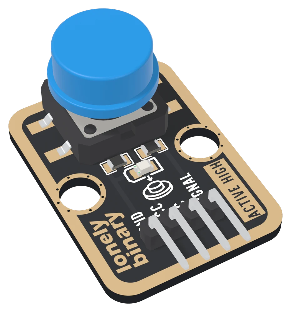
| Switch | 12 × 12 mm SMD tactile switch (USAKRO UK-B0262), 0.3 mm travel, 12 mm blue cap; 14.35 mm tall overall |
| Pull-down | 10 kΩ from SIGNAL to GND, on the board. Released reads LOW, pressed reads HIGH |
| Press light | Red LED with a 1 kΩ resistor on SIGNAL. Lights while the button is down, about 3 mA from 5 V |
| Supply | 3.3 V or 5 V on VCC. Pressed, SIGNAL is at VCC, so use 3V3 beside an ESP32, ESP32-S3 or Pico and 5V beside an Uno |
| Pins to wire | 3 of the 4: GND, VCC and SIGNAL. NC is connected to nothing on the board |
| Header | 4-pin right-angle male, 2.54 mm pitch: GND, VCC, NC, SIGNAL, with GND on the square pad |
| Switch rating | 12 V DC, 50 mA; contact resistance 100 mΩ max; rated for 70 000 to 100 000 presses depending on force |
| Board | 22.4 × 30.4 mm, two 4.8 mm mounting holes 16 mm apart |
| In the box | 1 × TK04 block. It also ships inside the TinkerBlock kits |
What it is
A 12 mm tactile switch, a 10 kΩ pull-down resistor, and a red LED that lights while the button is down. Released, the pull-down holds SIGNAL at 0 V and your board reads LOW. Pressed, the switch connects SIGNAL to VCC and your board reads HIGH. The front of the board says ACTIVE HIGH, and the back says WORKS ONLY WHILE PRESSED: let go and it is LOW again.
Reading it is one call to digitalRead. Reading it correctly takes one more
idea. A mechanical contact does not close once: it bounces, making and
breaking a few times in the first milliseconds of a press, and a sketch
reading the pin in a fast loop sees every one. A counter wired naively to this
button goes up by two or three now and then, which is exactly the kind of bug
that looks like bad hardware. The handbook below fixes it in a few lines.
VCC is the voltage your pin sees
The switch joins SIGNAL straight to VCC, so whatever is on VCC is what your pin receives when the button is down:
| Your board | VCC to | Pressed, SIGNAL is | Press light |
|---|---|---|---|
| Arduino Uno | 5V | 5 V | about 3 mA, bright |
| ESP32, ESP32-S3, Pico | 3V3 | 3.3 V | about 1.3 mA, a little dimmer |
Never 5V beside a 3.3 V board. With VCC unconnected, the button does nothing and the light never comes on. The LED currents are worked out from a red LED's typical forward voltage, about 2.0 V, rather than measured.
Which pin is which
Button side up, header at the bottom, reading left to right:
| GND | to your board's GND | the square pad: count from here |
| VCC | to 3V3 or 5V | your board's logic voltage |
| NC | nothing | not connected on the board |
| SIGNAL | to a digital input | HIGH while pressed |
The back prints TK04 PUSH BUTTON and WORKS ONLY WHILE PRESSED instead of pin names. Turned over, the square pad is on the right, and it is still GND.
Wiring, in three lines
- GND to your board's GND.
- VCC to 5V on an Uno, 3V3 on an ESP32, ESP32-S3 or Pico.
- SIGNAL to a digital pin: D2 on an Uno, GPIO 25 on an ESP32, GPIO 4 on an ESP32-S3, GP15 on a Pico.
Leave NC unconnected. Set the pin to INPUT, not INPUT_PULLUP: the pull-down
is already on the board.
Example
// The GPIO number SIGNAL is wired to.
// Uno: 2. ESP32: 25. ESP32-S3: 4. Pico: 15.
const int BUTTON_PIN = 4;

void setup() {
  Serial.begin(115200);
  pinMode(BUTTON_PIN, INPUT);   // the block has its own pull-down
}

void loop() {
  if (digitalRead(BUTTON_PIN) == HIGH) {   // HIGH is pressed
    Serial.println("pressed");
  } else {
    Serial.println("released");
  }
  delay(200);
}from machine import Pin
import time
# The GPIO number SIGNAL is wired to. ESP32: 25. ESP32-S3: 4. Pico: 15.
button = Pin(4, Pin.IN) # no pull: the block has its own
while True:
if button.value() == 1: # 1 is pressed
print("pressed")
else:
print("released")
time.sleep_ms(200)Where to start
The handbook below is nine short articles, each with a working figure. The first read is the whole build in three wires and a few lines.
If your counter goes up by more than one per press, read why one press counts as several and then debouncing with millis().
And before plugging it into an ESP32, VCC sets the voltage is the one page that protects the board.
When it doesn’t work
- Does it read HIGH or LOW when pressed?
- HIGH. The board has a 10 kΩ pull-down, not a pull-up: released, SIGNAL sits at 0 V and reads LOW; pressed, the switch connects it to VCC and it reads HIGH. The front of the board says ACTIVE HIGH. Sketches written for pull-up button boards test for LOW and get this block backwards.
- Should VCC go to 3V3 or 5V?
- To your board's logic voltage: 3V3 on an ESP32, ESP32-S3 or Pico, 5V on an Uno. Pressed, the switch connects SIGNAL straight to VCC, so the voltage on VCC is the voltage your pin receives. 5V on a 3.3 V board's pin is past its rating on every press.
- INPUT or INPUT_PULLUP?
- INPUT. The block brings its own pull-down. The chip's internal pull-up would fight it and leave the released level somewhere around a volt, which no datasheet promises to read as LOW. In MicroPython, Pin(pin, Pin.IN) with no pull argument.
- One press counts as several.
- Contact bounce, and it is not a fault: the metal contacts make and break a few times in the first few milliseconds of every press. Believe a change only once the pin has held still for about 20 ms. The handbook's debounce sketch does it with millis() and no library.
- It never reads pressed.
- Press and look at the red LED. If it stays dark, VCC or GND is not connected, or the cable is one pin over. If it lights, the block is fine and SIGNAL is on a different pin from the one your sketch reads.
- It reads presses nobody made.
- SIGNAL is not reaching your pin, so the pin is floating: check the SIGNAL wire. Then check the sketch uses INPUT, not INPUT_PULLUP.